
555 Music lantern controller circuit diagram
The circuit operates by first capturing sound through microphones, which convert acoustic signals into electrical signals for processing. The 555 timer is configured in astable mode, generating a continuous square wave output that serves as a clock signal for the CD4017 counter. The timing components are selected to allow for a flexible oscillation period, which can be adjusted to suit the desired timing of the light and sound synchronization.
The CD4017 counter is a decade counter that counts the clock pulses and activates its outputs sequentially. Each output corresponds to a specific timing interval, allowing for a precise control of the lighting sequence. The connection of the reset terminal allows for the counter to be reset after reaching the maximum count, ensuring that the sequence can repeat indefinitely.
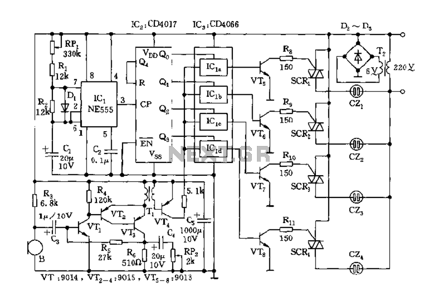
The analog switches (CD4066) are utilized to route the strobe signals to the respective outputs, effectively controlling the activation of the SCRs. These SCRs are used to switch the power to the lights, enabling them to flash in sync with the music. The overall design ensures that the audio and visual elements are harmoniously integrated, providing an engaging experience through synchronized music and lighting effects. The careful selection of components and their configuration allows for a versatile and dynamic performance, suitable for various applications such as entertainment systems, stage performances, or interactive installations.Controller as shown, including the acoustic-electric conversion and amplification circuit, a clock pulse generator, counting circuit and control circuit. It controls four accom panying music and lights flashing light. Microphones MIC song will sound into electrical signals, VT1 ~ VT4 was added to quad analog switch IC3 (CD4066). 555 and RP1, R1, R2, D1, C1 and other components astable multivibrator t charge 0.693 (RP1 + R1) C1 t put 0.693R2C1 T 0.693 (RP1 + R1 + R2) C1 Oscillation period T illustrated parameters vary within the range of 0.5 to 5 seconds.
3-pin output 555 added to the IC2 as a CP pulse. IC2 using CMOS type decimal counter/pulse distributor CD4017, under the clock CP action, Q0 (3 feet), Q1 (2 feet), Q2 (4 feet) Q3 (7 feet), Q4 (10 feet) high power have emerged level pulse, and Q4 was added to a reset terminal R (15 feet), the circuit becomes a ring counter circuit. Output Q0 ~ Q3 will in turn four analog switches CD4066 strobe signal sequentially added to the Song VT5, VT6, VT7, VT8, and sequentially turned on, SCR1 ~ SCR4 turn trigger conduction, followed by a power socket lights, lanterns order lights, with melodious music, lights flashing brilliance.
Related Circuits
The circuit comprises a 3-stage resistor-capacitor coupled amplifier. When ring button S2 is pressed, the amplifier circuit formed around transistors T1 and T2 gets converted into an asymmetrical astable multivibrator generating ring signals. These ring signals are amplified by...

The DTMF decoder can be powered by a 9V battery or through a parallel printer port. It is capable of detecting and displaying all 16 DTMF digits on a computer screen in real-time. The accompanying Windows program can run...
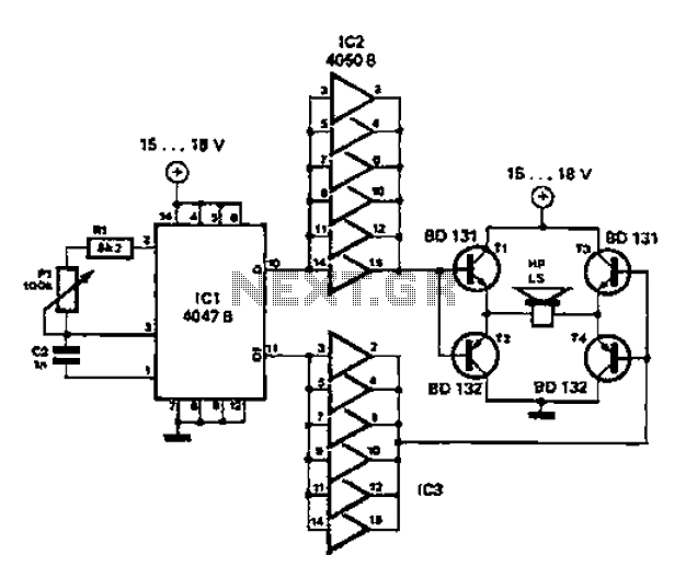
A low-cost and straightforward repellent circuit can be utilized for deterring rats, mice, and other animals, as illustrated in the electronic figure below. The circuit employs a CMOS integrated circuit of type 4047, which functions as a relaxation oscillator....
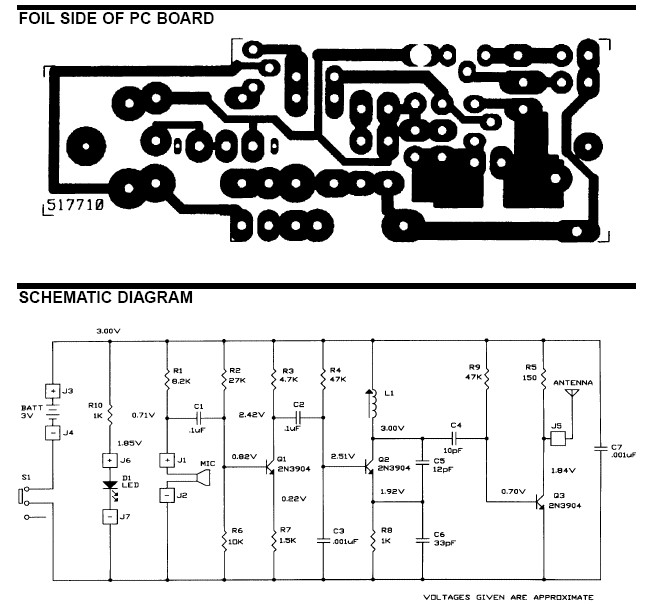
The frequency range for the FM transmission band is 90 MHz (megahertz, or 90 million cycles per second). Due to the variable tuned circuit in the FM transmitter, it can be tuned to a specific frequency within the local...
This circuit functions as a night lamp when a wall mains socket is unavailable for plugging in a continuously operating small neon lamp device. To minimize battery consumption, it utilizes a single 1.5V cell, and a simple voltage doubler...
The Clock Controller was designed as an exemplary application of the C programming language to manage timer0 interrupts, control a 7-segment LED display, and perform keypad scanning. It offers a 1-bit sink current output suitable for driving devices such...
Warning: include(partials/cookie-banner.php): Failed to open stream: Permission denied in /var/www/html/nextgr/view-circuit.php on line 713
Warning: include(): Failed opening 'partials/cookie-banner.php' for inclusion (include_path='.:/usr/share/php') in /var/www/html/nextgr/view-circuit.php on line 713