
555 Timer as an A/D converter
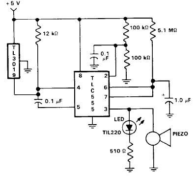
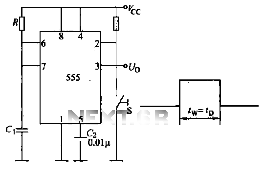
The 555 timer IC is a versatile device widely used in various timing applications. In this circuit configuration, the timer operates in a monostable mode, producing a pulse output based on the input voltage and the capacitor's charge. The pulse width can be finely tuned by altering the input voltage, allowing for precise voltage measurements.
The calibration process is critical for ensuring accurate readings. By establishing a reference voltage and calculating the coefficient, the circuit can reliably convert pulse counts into voltage values. The relationship between the pulse width and the input voltage is leveraged to create a linear approximation of the voltage measurement, making it suitable for integration with microcontroller platforms like the Basic Stamp.
The implementation of debug lines is essential for monitoring performance during the calibration process. It facilitates real-time adjustments and ensures that the system operates within its specified accuracy range. Furthermore, the limitations regarding voltage measurement below 5 volts must be accounted for, as they may affect the applicability of this circuit in lower voltage environments.
Overall, this circuit exemplifies a practical application of the 555 timer in voltage measurement, demonstrating its effectiveness and reliability when properly calibrated and utilized within its operational parameters.The 555 timer will put out positive pulses. The pulse width is inversely proportional to the difference in voltage between the voltage at "ANALOG IN" and the voltage of the 4. 7uF capacitor(let`s say 2. 5 volts). To calibrate this circuit, hook it up to a Basic Stamp measuring positive pulses, and give the circuit a known voltage.
Let`s say you get the number 2092 when you give the circuit 15 volts. Your coefficient is 2092 * (15 - 2. 5) = 26150. Now you are ready to measure voltage with your Basic Stamp. Use the formula: voltage = 26150/pulse + 2. 5. You will have to modify this to work within the limits of the Basic Stamp`s math. The accuracy of this circuit rivals many digital voltmeters within the range I tested it (6 volts to 18 volts), about the same as a 10 bit A/D converter. The accuracy will shift with the processor clock and the +5 supply, so it is pretty good. Conversion time is under 1/10 second. Please note it will not measure voltages below 5 volts. Also, check the accuracy of your +5 volts. If it is 5. 2 volts, you will need to use 2. 6 in the formula. `uncomment the debug lines to get pulse value while calibrating loop: `debug cls pulsin 0, 1, w2 `I used pin 0 `debug w2 w1=26150 `This is the coefficient you will need to calibrate.
w4=w1/w2 w3=w4*100 `I am going to get around the integer-only Stamp math. w4=w2*w4 w1=w1-w4*10 `remember the Stamp has left-to-right math w4=w1/w2 w3=w4*10+w3 w4=w2*w4 w1=w1-w4*10 w4=w1/w2 w3=w4+w3 w3=w3+250 `250 is really 2. 5 volts debug w3, "volts * 100" `we get a reading in hundredths of volts goto loop 🔗 External reference
Related Circuits
Telephones are declining globally; however, India has over 350 million mobile phone users, alongside a significant number of traditional telephone users. This telephone timer is designed to save costs by controlling unnecessary time spent during phone calls. This simple...
This door open alarm electronic project is designed using a linear hall effect device and a 555 timer circuit. The project utilizes the TL3103 linear hall effect device for detecting the angle of rotation. The TL3103 is positioned within...
This application note details the design of a 50-watt, isolated, forward converter, utilizing the MAX8540 synchronizable, high-frequency, current-mode PWM controller. The schematic design of the 50-watt isolated forward converter using the MAX8540 involves several key components and stages to ensure...

The super dimmer is an improved version compared to the standard dimmer currently in use. Testing its performance will provide a clearer understanding of its advantages. The super dimmer operates using advanced technology that allows for finer control over...

This circuit can be connected to any existing calculator battery using a push-on automatic switch, allowing it to function as a stopwatch while the calculator is not in use. The circuit utilizes a 555 timer configured in monostable mode to...
Introduction to the circuit schematic depicted in Figure 3-3. In this configuration, the 555 timer is utilized in a monostable mode, typically activated by a normally open push button switch. The circuit operates in an S-shaped state, where the...