
555 timer reverse polarity 2
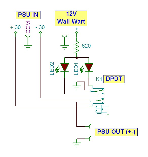
A dual power supply configuration, typically indicated as +V and -V, allows for the use of various components, including relays, within electronic circuits. An SPDT relay is a versatile switching device that can connect one common terminal to one of two other terminals, enabling the control of multiple circuits with a single relay. This functionality is particularly useful in applications requiring the switching of power or signals between different paths.
In this context, the choice between an electromechanical relay and a solid-state relay (SSR) should be considered based on the application requirements. An electromechanical relay uses an electromagnetic coil to operate a mechanical switch, offering the advantage of isolation between the control and load circuits. However, it may have limitations in terms of switching speed and durability compared to solid-state options.
Solid-state relays, on the other hand, utilize semiconductor devices to perform switching operations without moving parts, resulting in faster response times, longer lifespans, and reduced noise generation. They are ideal for applications where rapid switching and high reliability are essential.
When designing a circuit that incorporates an SPDT relay, attention must be given to the relay's specifications, such as coil voltage, contact ratings, and switching speed. Additionally, the circuit should include protection components, such as diodes for flyback protection, to prevent voltage spikes from damaging the relay or other components in the circuit. Proper layout practices and component selection will ensure the reliability and efficiency of the relay-based switching mechanism in the overall electronic design.Originally Posted by CDRIVE Thanks for clarifying that. Since you have a dual (+-) supply a SPDT relay will suffice. Do you want a solid state.. 🔗 External reference
Related Circuits
A timer is being developed for circuit training or boxing training. The timer does not require any external input, except for a reset function. The project can be simplified using a microcontroller, such as the PIC12F635, which is cost-effective...
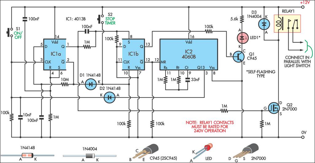
This 9-minute timer switch can be utilized to control lighting in a toilet or bathroom. The timer is activated by pressing switch S1 and deactivated by pressing S1 again. If the timer is not manually turned off, the light...
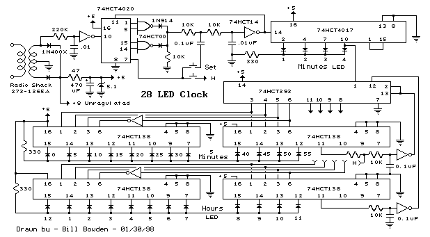
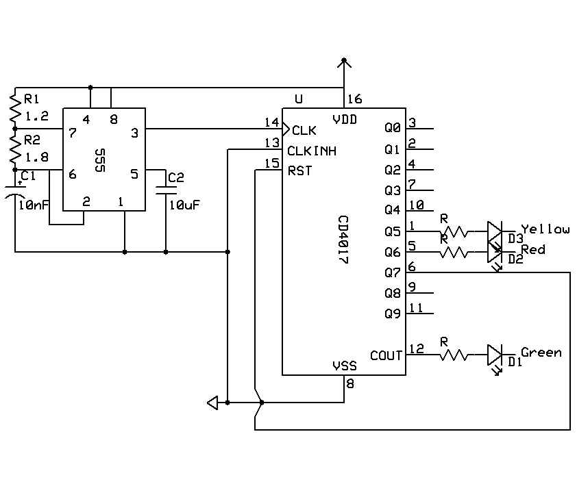
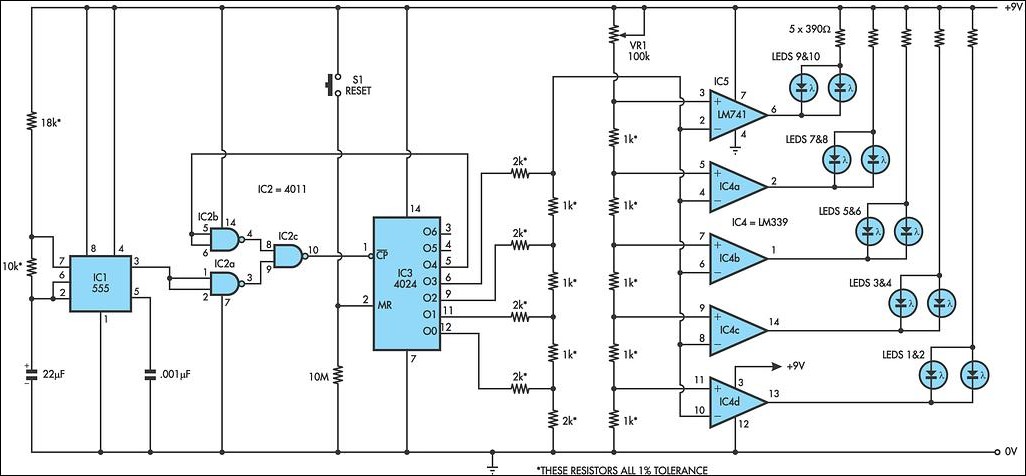
This is a programmable clock timer circuit that utilizes individual LEDs to signify hours and minutes. Twelve LEDs can be arranged in a circular formation to represent the 12 hours of a clock face, while an additional 12 LEDs...
This LED circuit replicates the initial LED sequence currently utilized by FISA for Formula One racing. It can also be employed with slot car sets, such as HO scale AFX, Life Like, or Tyco sets, or used in communication-controlled...
This calculator computes the resistor and capacitor values for a NE555 timer chip configured as an astable multivibrator (oscillator) or square wave generator. By entering the desired duty cycle and frequency, the calculator provides suitable values for the resistors...
In a stereo system, it is often important to determine whether the speakers are polarized. This can be especially problematic if the speaker cables lack polarity markings. The circuit described will assist in identifying the correct terminals for the...