
555 zinc-manganese batteries reduction charger circuit
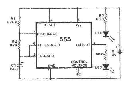
The astable multivibrator configuration of the 555 timer generates a continuous square wave output that can be used to control the charging process. The resistors R1 and R2, along with the capacitor C1, determine the frequency and duty cycle of the oscillation, which is crucial for maintaining an effective charging rate. The choice of resistor values directly affects the time the output remains high or low, and thus the charging current delivered to the battery.
The current-limiting resistor R6 is essential for protecting the circuit and the battery from excessive current during the charging process. The diode D1 is strategically placed to prevent any backflow of current from the battery to the charging circuit, ensuring that the battery discharges only when intended.
The operation of the regulator diode DW is critical for managing the charging state of the battery. When the battery voltage is below the set threshold, the circuit remains active, allowing for continuous charging. Once the battery reaches its full charge, the conduction of DW and the saturation of VT1 effectively disable the charging circuit, preventing overcharging and potential damage to the battery.
The LED indicator provides a visual cue to the user, signaling when the battery is fully charged. This feature is particularly useful in applications where monitoring the charging status is essential.
The reverse battery indicator D4 enhances the safety of the circuit by alerting the user to incorrect battery installation. This feature is vital in preventing damage to the circuit and ensuring proper operation.
The smoothing circuit formed by R5 and C3 helps to stabilize the voltage supplied to the charging circuit, filtering out any noise that may affect performance. This stabilization is particularly important in battery charging applications, where consistent voltage levels are necessary for optimal charging efficiency.
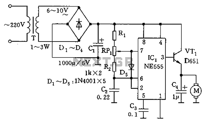
Overall, this circuit design is well-suited for applications requiring efficient battery charging, particularly for zinc-manganese batteries, while providing essential safety features and user indicators. The flexibility in selecting voltage sources and zener diodes allows for adaptability to various battery specifications. Circuit 555 as the core to form a astable multivibrator. Oscillation period T 0.693 (R1 + 2R2) C1 Icon parameter corresponding to the oscillation frequency of about 100Hz or so . Duty cycle is close to 1: 1 Therefore, the charger is charging pulse 555 output by R6 directly after the charging current limiting. D1 diode prevents battery discharge. DW for the regulator diode, when the battery is not fully charged, DW off, VT1 tube off, then reset terminal 555 was 4 feet high and 555 in oscillating state; when the battery is fully charged, DW conduction, VT1 saturated conduction tube pass, the 555 was 4 feet by leaving the low oscillation circuit suspension, automatic shutdown when the battery is full, at the same time, LED flashes, it indicates charged.
DW should be selected so that the regulator Ratings plus 0.7V VT1 tube PN junction, the battery slightly higher than the nominal value. Thus, by selecting a different voltage source Vdd (5 ~ 15V) and different zener diode, to meet the different number of battery charging requirements.
D4 is reverse battery indicator. R5, C3 composition smoothing circuit. The charge reduction is the use of pulse charging, zinc-manganese batteries for the resurrection of the reduction is good, but not used lead-acid batteries or rechargeable nickel-cadmium batteries.
Related Circuits
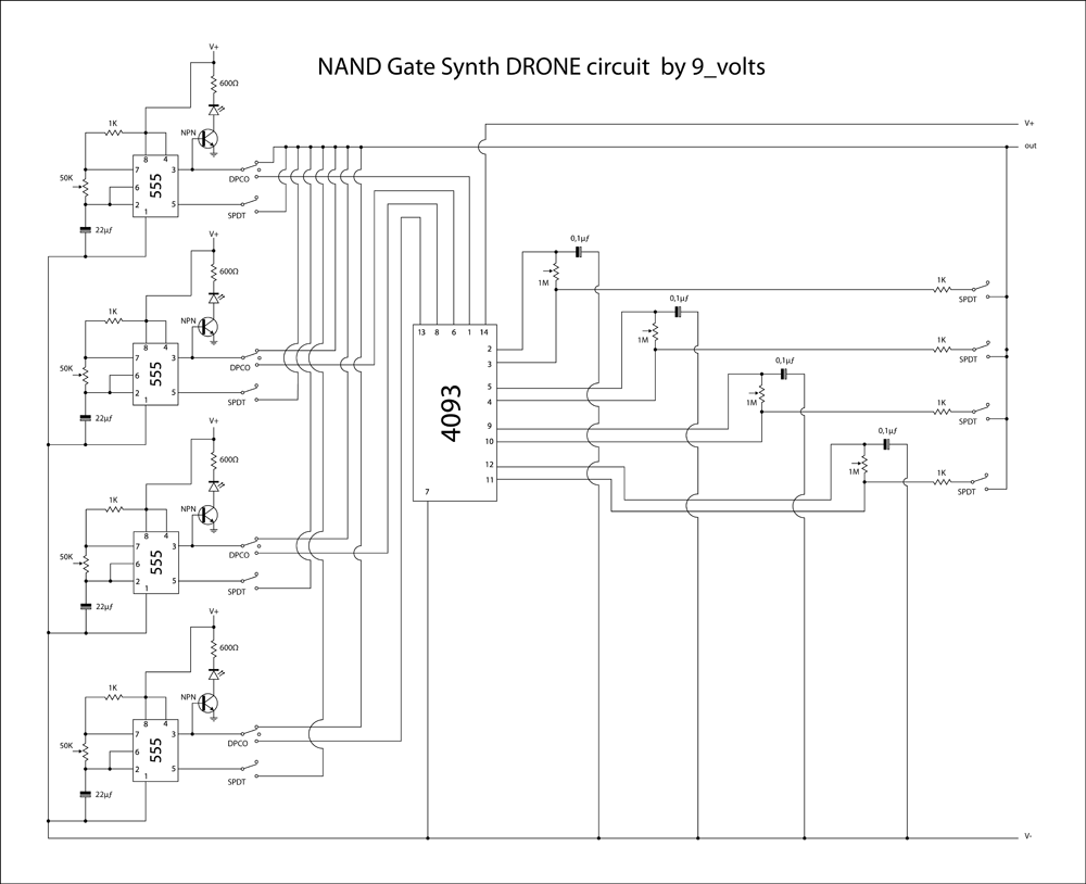
This is a brief jam session to explore the capabilities of a recently completed step sequencer. This device is quite enjoyable and expands creative possibilities. A detailed post with the circuit and instructions for building it will be provided...
The following circuit illustrates a 5 Zone Anti-Theft Circuit Diagram. This circuit is based on the CMOS 4050B IC. Features: the system may comprise in... The 5 Zone Anti-Theft Circuit utilizes the CMOS 4050B integrated circuit, which is a hex...
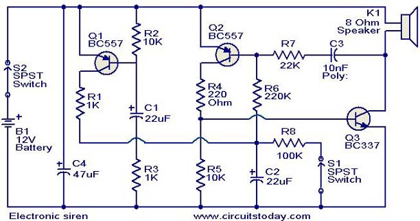
This is a compact electronic siren circuit based on three transistors. This circuit is suitable for incorporation with other alarm or siren projects such as burglar alarms, automatic factory sirens, or a simple push-to-on alarm. The electronic siren circuit...
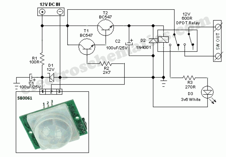
This circuit represents a general-purpose white LED security light equipped with a Passive Infrared (PIR) motion sensing mechanism. The core component of the circuit is the PIR sensor module SB0061, which is a pyroelectric sensor designed for human body...
An integrated circuit is precisely that: an integrated circuit. These small packages combine numerous individual components to perform a specific function. They vary in shape and size depending on their complexity. They are categorized into functions such as audio,...
The bearing fault detector circuit consists of a bearing detection sensor, a signal processing circuit, a transistor (V), an audio amplifier integrated circuit (IC2), a speaker (BL), an RC element, an integrated circuit (IC1), and a light-emitting diode (VL)....