
6 channel audio mixer
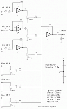
The 6-channel audio mixer circuit is structured to facilitate versatile audio mixing applications. Each of the three microphone channels typically includes a preamplifier stage, which amplifies the low-level signals from microphones to a usable level. The audio input channels are configured to accept line-level signals from various sources, ensuring compatibility with common audio devices.
The six potentiometers serve as variable resistors, providing individual volume control for each channel. This allows for precise adjustments to the audio levels, enabling the user to achieve a balanced mix. The output stage of the mixer combines the signals from all channels, which can then be sent to an amplifier or recording device.
The PCB design process involves several critical steps. First, the schematic of the circuit is created using PCB design software, which allows for the layout of components and routing of traces. Once the design is finalized, it is printed onto the chosen paper type. The adhesion of the printed design to the PCB is crucial; therefore, applying consistent heat with a hot iron plate ensures that the ink transfers effectively.
After the design is transferred, the PCB undergoes an etching process to remove excess copper, leaving behind only the desired circuit traces. This is typically done using a ferric chloride solution or similar etchant. Following etching, the PCB can be drilled for component placement, and components can be soldered onto the board to complete the assembly of the audio mixer.
This audio mixer circuit is suitable for various applications, including live sound reinforcement, recording studios, and home audio setups, providing users with the ability to manage multiple audio sources seamlessly.This is 6 Channel Audio Mixer circuit. 3 channel for microphone input and the others 3 channel for audio input like CD player, computer, or television. There will be 6 potensiometer to control the volume of each channel. Make a PCB in very easy steps. ! Create your PCB design using PCB designer software like Eagle, print out your design on photo p aper or glossy paper with laserjet printer. Stick the printed design on the PCB (copper side) and then heat it using hot iron plate. The ink will stick on the PCB and it will be ready for etching process. Note: If you don`t have laserjet printer, then you can print the design on standard paper. Copy the printed design at Copy Service around your location (with glossy paper). 🔗 External reference
Related Circuits
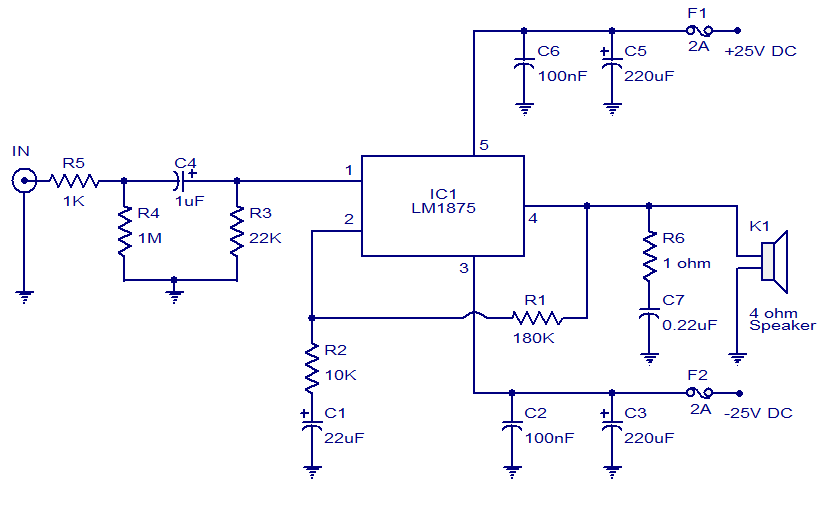
This weblog focuses on electronic circuit schematics, PCB design, DIY kits, and electronic project diagrams. The featured project is a 20W audio amplifier circuit based on the LM1875 audio amplifier IC from National Semiconductors. With a 25V power supply,...
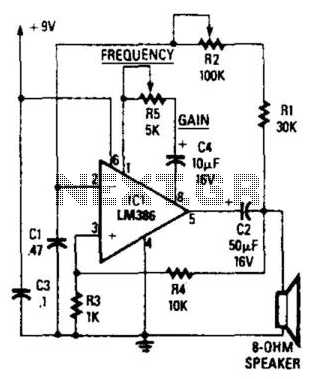
The circuit's frequency oscillation is given by the formula f = 2.8 / [Cix(i1 + i2)]. By utilizing the specified values, the output frequency can be adjusted from 60 Hz to 20 kHz by rotating potentiometer R2. A portion...
A 2 x 18W Hi-Fi Stereo Power Amplifier is designed using two TDA2030 integrated circuits (ICs). This amplifier features excellent input sensitivity, low distortion levels, stable operation, and comprehensive protection against overloads and output short circuits. It can serve...
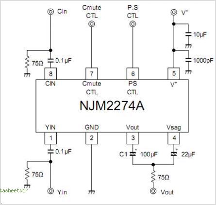
The NJM2574 is a low voltage video amplifier that includes a low-pass filter (LPF) circuit, a driver, and an internal clamp/bias function. It is designed to connect directly to a TV monitor using a composite input signal of 0.5V...
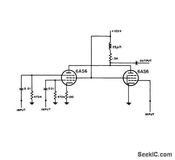
Distance markers and if signals are inserted at separate grids on one tube, while radar video from input 3 is impressed on the control grid of another pentode. In this circuit design, the integration of distance markers and intermediate...
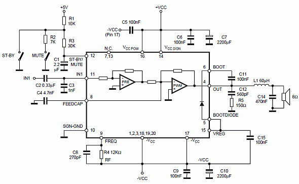
Class D audio power amplifier schematic diagram with TDA7480, capable of 10W output power at a load of 8Ω/4Ω and a total harmonic distortion of 10%. Requires a split-supply (max. ±20V). The Class D audio power amplifier utilizing the TDA7480...
Warning: include(partials/cookie-banner.php): Failed to open stream: Permission denied in /var/www/html/nextgr/view-circuit.php on line 713
Warning: include(): Failed opening 'partials/cookie-banner.php' for inclusion (include_path='.:/usr/share/php') in /var/www/html/nextgr/view-circuit.php on line 713