
6 static display circuit
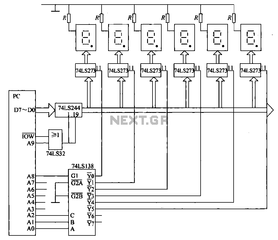
The static display circuit utilizes the 74LS244 as bus drivers to manage data flow to multiple display units. Each unit consists of an LED display latch, specifically the 74LS273, which is responsible for holding the data that will be visually represented. The connection between the data bus and the latches is facilitated by the 74LS244, which ensures that the data is transmitted accurately when the appropriate control signals are activated.
The address decoder, 74LS138, plays a critical role in this circuit by determining which latch should receive the data from the bus. It decodes the address signals and enables the corresponding latch based on the decoded output. The simultaneous activation of the IOW (Input/Output Write) signal and the A9 address line, both being low, triggers the 74LS244 to become operational. This configuration allows for precise control over which display is updated at any given time.
The sequential addressing of the display bits, ranging from 100H to 105H, indicates that there are six distinct latches in the circuit, each capable of holding its own data. When the control signals are correctly set, the 74LS244 transmits the relevant data from the data bus to the selected latch, allowing the LED display to reflect the intended output. This setup is particularly useful in applications requiring multiple visual outputs, such as scoreboards or status indicators, where real-time data representation is crucial.6 shows the static display circuit. Figure, 74LS244 as bus drivers, six figures show a public bus, each with an LED display martyrdom latch (such as 74LS273) connected to the code for latching display data to be displayed. Data is displayed on behalf of code from the data bus via 74LS244 to the input of each latch, recanalization specified by the address decoder 7,415,138± latch latches. 74LS244 bus driver by the IOW and A9 control, when the output instruction is executed so that Lai) W and Ag at the same time is low, 74LS244 to play on, transmitting data on the data bus corresponding to each display latches (74LS273) on.
In the circuit shown in the figure, from left to right each display bit address followed 100H, 101H, 10ZH, 103H, 104H, 105H.
Related Circuits
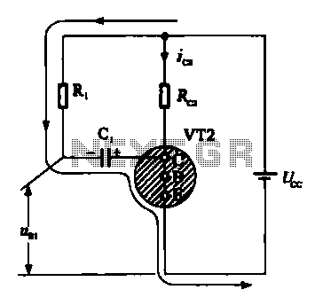
When VRI is off, 0 [2 is activated, allowing current to flow through RJ and Ci. When VT1 conducts, charging of C1 begins, causing it to discharge. This results in an inverting charge on C1, making the voltage positive,...
The receiver is based on a basic SA612 circuit. The local oscillator (LO) for the 20-meter band operates at approximately 9 MHz, with an intermediate frequency (IF) of 5.068 MHz. The IF filter employs two crystals and has a...
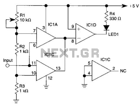
IC1-c functions as a non-inverting comparator, while IC1-a operates as an inverting comparator. Potentiometer R1 and fixed resistors R2 and R3 create a voltage divider chain that provides slightly different voltages to the two comparators. These voltages establish the...
This simple circuit tests speakers, microphones, transformers, and voltage. It is essentially a very low-frequency oscillator that generates extremely short, distinctive pulses. The sound produced is easy to hear and allows for precise localization, making it ideal for checking...
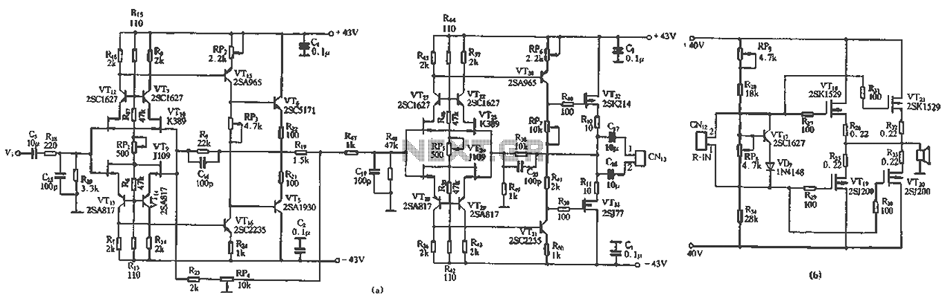
The circuit design features a unique technology and a reasonable structure utilizing all-discrete components with a Class A FET output. The complete circuit includes an input stage, an output stage, and a power level circuit to enhance performance, along...
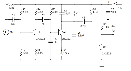
This FM wireless microphone is straightforward to construct and offers significant transmission capabilities, with a range of approximately 300 meters outdoors. Its compact component count and 3V operating voltage allow it to effectively penetrate multiple floors of an apartment...
Warning: include(partials/cookie-banner.php): Failed to open stream: Permission denied in /var/www/html/nextgr/view-circuit.php on line 713
Warning: include(): Failed opening 'partials/cookie-banner.php' for inclusion (include_path='.:/usr/share/php') in /var/www/html/nextgr/view-circuit.php on line 713