
60-70dB Decibel Meter schematic
When an audio signal is present, the 10uF capacitor connected to the diode will charge toward the peak audio level at the op-amp output at pin 1. As the volume increases, the DC voltage on the capacitor and also (+) comparator inputs will increase and the lamp will turn on when the (+) input goes above the (-) input. As the volume decreases, the capacitor discharges through the parallel 100K resistor and the lamps go out. You can change the response time with a larger or smaller capacitor.
This circuit requires a well filtered power source, it will respond to very small changes in supply voltage, so you probably will need a large filter capacitor connected directly to the 330 ohm resistor. I managed to get it to work with an unregulated wall transformer power source, but I had to use 4700uF. It worked well on a regulated supply with only 1000uF.
The circuit operates as a sound level indicator, utilizing an 8-ohm speaker or dynamic microphone to detect ambient sound levels in the range of 60 to 70 dB. The audio signal is amplified through a transistor stage followed by an LM324 operational amplifier, which consists of four op-amps in a single package. Three of these op-amps function as voltage comparators, each controlling an indicator light, such as an LED or incandescent bulb, that illuminates based on the detected sound pressure level.
The sensitivity of the circuit can be adjusted through a 500K potentiometer, allowing for calibration to a specific reference sound level. Each indicator light corresponds to a 3 dB increase in sound level, with all three lights illuminating when the sound level reaches approximately four times the threshold required to activate the first lamp. This creates a visual representation of sound intensity, with the first lamp indicating the reference level, the second lamp indicating a doubling of sound intensity, and the third lamp indicating a fourfold increase.
In the absence of an audio signal, the circuit stabilizes at a DC voltage of approximately 4 volts at the output of the first op-amp. The comparator inputs are designed to detect voltage levels that are slightly lower due to the forward voltage drop of the 1N914 diode. The reference voltages for the comparators are established using resistive voltage dividers, with values of 560 ohms and 750 ohms setting the thresholds for the second and third lights.
When an audio signal is present, a 10uF capacitor connected to the diode charges in response to the peak audio levels detected at the op-amp output. As the sound level increases, the voltage across the capacitor and the comparator inputs rise, triggering the indicator lamps to illuminate. Conversely, when the sound level decreases, the capacitor discharges through a parallel 100K resistor, causing the lamps to turn off.
The circuit requires a stable power supply with adequate filtering to ensure reliable operation. Fluctuations in supply voltage can significantly affect performance, necessitating the use of a large filter capacitor, typically around 4700uF for unregulated sources or 1000uF for regulated supplies. This design consideration is critical for maintaining consistent operation and accurate sound level indication.The circuit below responds to sound pressure levels from about 60 to 70 dB. The sound is picked up by an 8 ohm speaker, amplified by a transistor stage and one LM324 op-amp section. You can also use a dynamic microphone but I found the speaker was more sensitive. The remaining 3 sections of the LM324 quad op-amp are used as voltage comparators and drive 3 indicator LEDs or incandescents which are spaced about 3dB apart.
An additional transistor is needed for incandescent lights as shown with the lower lamp. I used 12 volt, 50mA lamps. Each light represents about a 3dB change in sound level so that when all 3 lights are on, the sound level is about 4 times greater than the level needed to light one lamp. The sensitivity can be adjusted with the 500K pot so that one lamp comes on with a reference sound level.
The other two lamps will then indicate about a 2X and 4X increase in volume. In operation, with no input, the DC voltage at pins 1,2 and 3 of the op-amp will be about 4 volts, and the voltage on the (+) inputs to the 3 comparators (pins 5,10,12) will be about a half volt less due to the 1N914 diode drop. The voltage on the (-) comparator inputs will be around 5.1 and 6.5 which is set by the 560 and 750 ohm resistors.
When an audio signal is present, the 10uF capacitor connected to the diode will charge toward the peak audio level at the op-amp output at pin 1. As the volume increases, the DC voltage on the capacitor and also (+) comparator inputs will increase and the lamp will turn on when the (+) input goes above the (-) input.
As the volume decreases, the capacitor discharges through the parallel 100K resistor and the lamps go out. You can change the response time with a larger or smaller capacitor. This circuit requires a well filtered power source, it will respond to very small changes in supply voltage, so you probably will need a large filter capacitor connected directly to the 330 ohm resistor.
I managed to get it to work with an unregulated wall transformer power source, but I had to use 4700uF. It worked well on a regulated supply with only 1000uF. 🔗 External reference
Related Circuits
The circuit is connected in parallel with the output of a power amplifier and provides the signal level from the output. By adjusting the resistance R1 in the input circuit, the power indication can be adapted to the resistance...
For a candle to burn, we need a heat source (the flame of a match) and to extinguish it, you do it just to blow out. The following circuit behaves similarly. If you use your fingers heats the thermistor,...
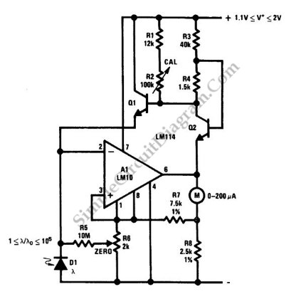
This is a portable light-level meter circuit with a five-decade dynamic range. It utilizes a single-cell battery as the power supply. To calibrate this circuit, The portable light-level meter circuit is designed to measure light intensity across a wide...
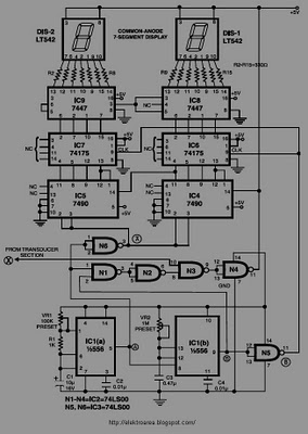
This circuit is designed to display the speed of a vehicle in kilometers per hour (km/h). An opaque disc is mounted on the spindle connected to the front wheel of the vehicle. The disc features evenly spaced holes along...
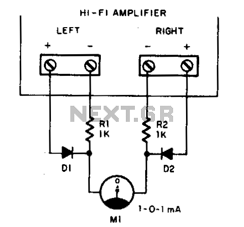
Play any stereo disc or tape and then set the amplifier to mono. Adjust the left and right channel balance until meter Ml indicates zero; then the left and right output levels are identical. To implement a system that allows...
A user has recently purchased the Dantimax that mic preamp and is seeking guidance on how to install a VU meter. The integration of a VU meter with the Dantimax mic preamp can enhance audio monitoring by providing visual feedback...
Warning: include(partials/cookie-banner.php): Failed to open stream: Permission denied in /var/www/html/nextgr/view-circuit.php on line 713
Warning: include(): Failed opening 'partials/cookie-banner.php' for inclusion (include_path='.:/usr/share/php') in /var/www/html/nextgr/view-circuit.php on line 713