
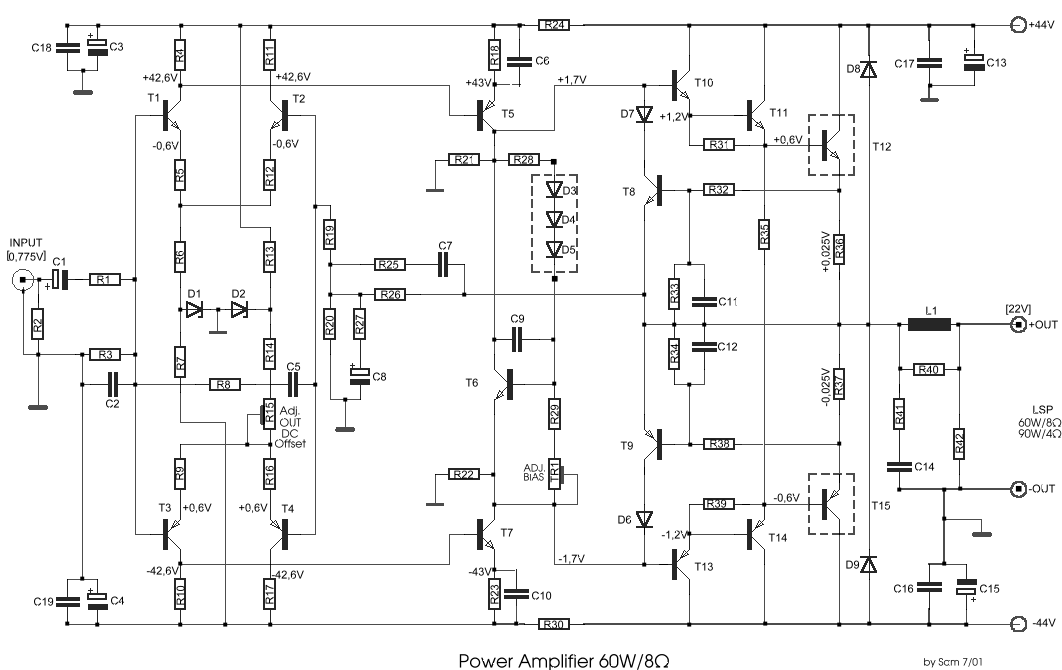
60 Watt Audio Power AmplifierCircuit
The described circuit is a high-quality power amplifier capable of delivering 60 to 90 watts of output power, utilizing advanced MosFet technology for robust performance. The IRFP240 and IRFP9240 MosFets serve as the output stage, providing high efficiency and thermal stability. The inclusion of high-voltage Motorola transistors in the earlier stages of the circuit enhances the overall fidelity and reliability of the amplifier.
The design allows for a supply voltage of ±40V, which is ideal for achieving a balance between performance and component longevity. For users seeking higher output, the option to increase the supply voltage to ±50V is available, facilitating an approach to the 100W output target into an 8-ohm load. This flexibility makes the amplifier suitable for a variety of audio applications, from home audio systems to professional sound reinforcement setups.
The circuit also incorporates a unique modification to improve quiescent current stability. The original three-diode configuration has been adapted by replacing two diodes with a red LED, which is known to provide better thermal stability. This modification is particularly beneficial in maintaining consistent performance across varying temperature conditions.
Capacitance values for the power supply are critical; the suggested minimum of 10,000 µF for C1 and C2 ensures adequate filtering for mono operation. However, increasing these values in stereo configurations is recommended to enhance performance and reduce noise.
Proper grounding techniques are emphasized to mitigate hum and ground loops, which are common issues in audio systems. Specific grounding points have been identified for critical components, ensuring a clean signal path and minimizing interference.
This amplifier design not only celebrates the milestone of the hundredth design but also reflects a commitment to quality and performance, catering to both audiophiles and professionals in the field. The availability of a matching modular preamplifier further complements the amplifier, providing a complete audio solution.To celebrate the hundredth design posted to this website, and to fulfil the requests of many correspondents wanting an amplifier more powerful than the 25W MosFet, a 60 - 90W High Quality power amplifier design is presented here. Circuit topology is about the same of the above mentioned amplifier, but the extremely rugged IRFP240 and IRFP9240 MosF
et devices are used as the output pair, and well renowned high voltage Motorola`s transistors are employed in the preceding stages. The supply rails voltage was kept prudentially at the rather low value of + and - 40V. For those wishing to experiment, the supply rails voltage could be raised to + and - 50V maximum, allowing the amplifier to approach the 100W into 8 Ohm target: enjoy!
A matching, discrete components, Modular Preamplifier design is available here: Modular Audio Preamplifier. In the original circuit, a three-diode string was wired in series to R10. Two of these diodes are now replaced by a red LED in order to achieve improved quiescent current stability over a larger temperature range.
Thanks to David Edwards of LedeAudio for this suggestion. The value suggested for C1 and C2 in the Power Supply Parts List is the minimum required for a mono amplifier. For optimum performance and in stereo configurations, this value should be increased: 10000 µF is a good compromise.
A correct grounding is very important to eliminate hum and ground loops. Connect to the same point the ground sides of R1, R3, C2, C3 and C4 and the ground input wire. Connect R7 and C7 to C11 to output ground. Then connect separately the input and output grounds to the power supply ground. 🔗 External reference
Related Circuits
The purpose of this report is to provide background and findings of our senior project. We will discuss four steps that we used to complete our final project. The four steps of our project were research and development, design,...
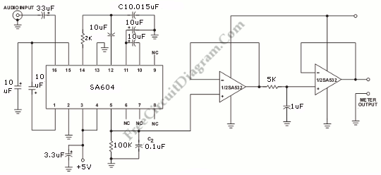
This circuit is an Audio Decibel Level Meter that utilizes the SA604 integrated circuit, which is designed as an RF device and also serves as a Received Signal Strength Indicator (RSSI). In cellular radio applications, the radio's microcomputer continuously...
This circuit was designed and manufactured in the 1980s. Since then, it has operated without issues. There are no significant constructional challenges, aside from the usual considerations: ensuring the appropriate power supply voltage, selecting a suitable heatsink, and properly...
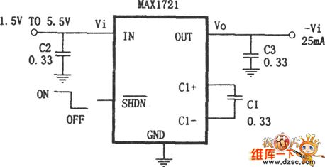
The MAX732/733 is a DC-DC current PWM step-up regulator. The MAX732 has an output voltage of +12V with a maximum output current of 200mA and an output voltage range of +4.0V to +9.3V. The MAX733 features an output voltage...
This is a 25 Watt basic power amplifier designed to be relatively easy to build at a reasonable cost. It offers better performance than standard STK module amplifiers commonly found in mass-market stereo receivers. The original design was created...
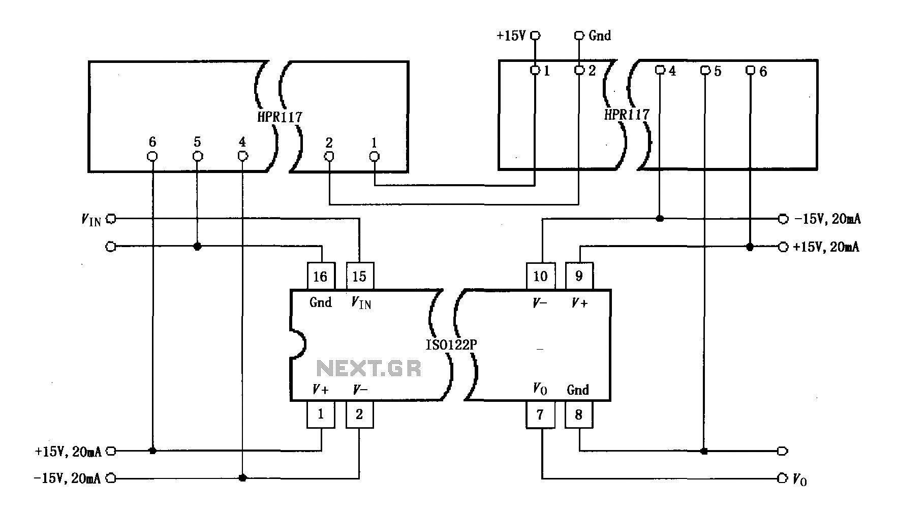
Power isolation is demonstrated for the ISO122P / 124, which features a three-port amplifier. The circuit also utilizes precision analog isolation amplifiers. The ISO122P / 124 isolation amplifier is a cost-effective solution, and the HPR117 DC/DC converter component provides...
Warning: include(partials/cookie-banner.php): Failed to open stream: Permission denied in /var/www/html/nextgr/view-circuit.php on line 713
Warning: include(): Failed opening 'partials/cookie-banner.php' for inclusion (include_path='.:/usr/share/php') in /var/www/html/nextgr/view-circuit.php on line 713