
60Hz-power-inverter
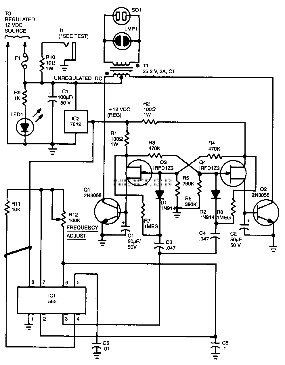
Capacitor C5 and potentiometer R12 determine the frequency of the output signal at pin 3 of IC1, the 555 oscillator. The output signal is differentiated by C3 and C4 before it is input to the base of power transistors Q1 and Q2 via diodes D1 and D2, respectively. The signal from IC1 is adjusted to 120 Hz because the flip-flop formed by transistors Q3 and Q4 divides the frequency by 2. When Q3 is on, the base of Q1 is connected via R1 to the regulated 12-V supply. Then, when the flip-flop changes states, Q4 is turned on and the base of Q2 is connected to the 12-V supply through R2. The 100 mA base current allows Q1 and Q2 to alternately conduct through their respective halves to the transformer's secondary winding. To eliminate switching transients caused by the rapid switching of Q3 and Q4, capacitors C1 and C2 filter the inputs to the base of Q1 and Q2, respectively. Power for the unit comes from an automobile's 12V system or from a storage battery. The power is regulated by IC2, a 7812 regulator. LED1, connected across the 12-V input, can be used to indicate whether power is being fed to the circuit. The neon pilot lamp, LMP1, shows the presence or absence of output power.
The circuit described utilizes a 555 timer IC (IC1) configured as an astable multivibrator, where the timing components, capacitor C5 and potentiometer R12, set the frequency of the output signal. This output is crucial as it drives a pair of power transistors (Q1 and Q2) that control the current flowing to a transformer, thereby generating the necessary output voltage for the application. The differentiation of the output signal through capacitors C3 and C4 ensures that the transistors are triggered effectively, allowing for smooth operation.
Transistors Q1 and Q2 are configured in a push-pull arrangement, which enables them to alternate their conduction states. This alternation is controlled by a flip-flop circuit made from transistors Q3 and Q4, which divides the frequency output from the 555 timer by two. When Q3 is activated, it provides a base current to Q1 through resistor R1, allowing it to turn on. Conversely, when Q4 is activated, it provides base current to Q2 via resistor R2. The design allows for a 100 mA base current to flow, ensuring that both transistors can handle the load required to drive the transformer effectively.
To mitigate switching noise, capacitors C1 and C2 are placed at the bases of Q1 and Q2, respectively. These capacitors filter out transients that may arise from the rapid switching of the flip-flop transistors, ensuring stable operation of the power stage. The circuit is powered by a 12V supply, which can be sourced from an automobile's electrical system or a storage battery, providing versatility in its application.
Voltage regulation is achieved through IC2, a 7812 voltage regulator, which maintains a steady output voltage for the circuit's operation. Additionally, LED1 serves as a power indicator, illuminating when the circuit is powered, while the neon pilot lamp LMP1 indicates the presence or absence of output power, providing visual feedback for the user. This circuitry is well-suited for applications requiring controlled output from a 12V source, ensuring reliability and efficiency in operation.Capacitor C5 and potentiometer R12 determine the frequency of the output signal at pin 3 of IC1, the 555 oscillator. The output signal is differentiated by C3 and C4 before it"s input to the base of power transistors Q1 and Q2 via diodes D1 and D2, respectively.
The signal from !C1 is adjusted to 120Hz, because the flip-flop formed by transistors Q3 and Q4.divides the frequency by 2. When Q3 is on, the base of Q1 is connected via R1 to the regulated 12-V supply. Then, when the flipflop changes states, Q4 is turned on and the base of Q2 connected to the 12-V supply through R2. The 100 mA base current allowsQ1 and Q2 to alternately conduct through their respective halves to the transformer"s secondary winding.
To eliminate switching transients caused by the rapid switching of Q3 and Q4, capacitors C1 and C2 filter the inputs to the base of Q1 and Q2 respectively. Power for the unit comes from an automobile"s 12V system or from a storage battery. The power is regulated by IC2, a 7812 regulator. LED1, connected across the 12-V input, can be used to indicate whether power is being fed to the circuit.
The neon pilot lamp, LMP1, shows a presence or absence of output power. 🔗 External reference
Warning: include(partials/cookie-banner.php): Failed to open stream: Permission denied in /var/www/html/nextgr/view-circuit.php on line 713
Warning: include(): Failed opening 'partials/cookie-banner.php' for inclusion (include_path='.:/usr/share/php') in /var/www/html/nextgr/view-circuit.php on line 713