
60W Guitar Amplifiers
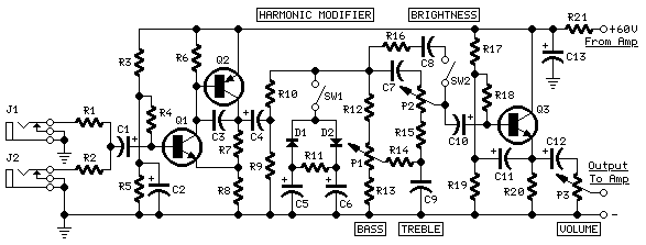
This power amplifier design is characterized by its efficient use of a single power supply, which simplifies the overall architecture while maintaining high performance. The choice of a 60V single-rail supply is particularly advantageous for guitar amplifiers, as it allows for substantial output levels without the complexity associated with dual-rail supplies. Capacitor coupling serves not only to block DC voltage from reaching the speakers but also to enhance the amplifier's response to dynamic audio signals, making it suitable for musical applications.
The preamplifier stage, powered by the same rails, benefits from a two-transistor gain block configuration. This arrangement is capable of delivering significant voltage output while providing a robust input overload capability, essential for handling the high signal levels typical of electric guitar performances. The selection of output transistors is critical; while Darlington pairs are known for their high current gain, they may introduce unnecessary complexity and size. The suggested alternatives, MJ11014, MJ11013, TIP142, and TIP147, provide a more suitable balance between performance and size for this application.
The diodes used in the circuit play a pivotal role in shaping the harmonic content of the output signal. The choice between Schottky-barrier diodes and silicon diodes influences the tonal characteristics of the amplifier. Schottky diodes tend to produce a sharper harmonic response, while 1N4148 diodes yield a softer, more musical distortion, which may be preferred in a guitar amplifier.
Thermal management is another critical aspect of this design. The close thermal coupling of the sensing transistor (Q2) to the output transistors ensures accurate thermal tracking, which is vital for maintaining performance and reliability. The use of a TO126 package facilitates this close contact, allowing for effective heat dissipation.
Finally, the adjustment of resistor R9 is necessary to achieve the desired output characteristics. By measuring the voltage drop across this resistor and fine-tuning it to approximately half the voltage supply, optimal performance can be attained. Utilizing an oscilloscope during this process will provide visual feedback, ensuring that the output waveform is symmetrical and that the amplifier can deliver maximum power without distortion. This careful calibration is essential for achieving the best possible sound quality in a high-performance guitar amplifier.This design adopts a well established circuit topology for the power amplifier, using a single-rail supply of about 60V and capacitor-coupling for the speaker(s). The advantages for a guitar amplifier are the very simple circuitry, even for comparatively high power outputs, and a certain built-in degree of loudspeaker protection, due to capacitor
C8, preventing the voltage supply to be conveyed into loudspeakers in case of output transistors` failure. The preamp is powered by the same 60V rails as the power amplifier, allowing to implement a two-transistors gain-block capable of delivering about 20V RMS output.
This provides a very high input overload capability. The Darlington transistor types listed could be too over sized for such a design. You can substitute them with MJ11014 (Q3) and MJ11013 (Q4) or TIP142 (Q3) and TIP147 (Q4). D1 and D2 can be any Schottky-barrier diode types. With these devices, the harmonic modifier operation will be hard. Using for D1 and D2 two common 1N4148 silicon diodes, the harmonic modifier operation will be softer. In all cases where Darlington transistors are used as the output devices it is essential that the sensing transistor (Q2) should be in as close thermal contact with the output transistors as possible.
Therefore a TO126-case transistor type was chosen for easy bolting on the heatsink, very close to the output pair. R9 must be trimmed in order to measure about half the voltage supply from the positive lead of C7 and ground.
A better setting can be done using an oscilloscope, in order to obtain a symmetrical clipping of the output waveform at maximum output power. 🔗 External reference
Related Circuits
Buffers are a specific category of amplifiers, and power buffers are a subset of power amplifiers. The defining characteristics of all buffers include unity gain and a low impedance output, ideally accompanied by low distortion. When examining commercially available...
This is my reincarnation of the EH Small Clone and Roland CE-1. Unlike the Clone it has a proper depth control. It also has a switch to change between the CE-1 like 512 stage delay and the Clone's 1024...
The objective of this design is to create a Combo amplifier that was popular during the 1960s and 1970s. It is particularly effective as a guitar amplifier but can also perform well with various electronic musical instruments or microphones....
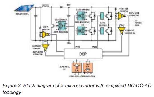
Both help improve efficiency and protect micro-inverters in photovoltaic (PV) solar applications. In 2009, the residential solar photovoltaic (PV) inverter market represented 90 percent of the total PV. The integration of micro-inverters in photovoltaic solar applications has significantly enhanced system...
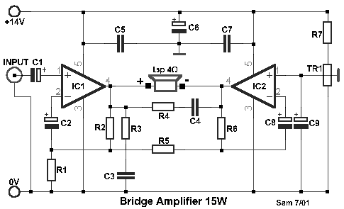
This is a compact collection of amplifiers configured in a bridge connection. The output power is low, making them suitable for general applications. They can be utilized with small active loudspeakers, car stereos, and similar devices. The only limitation...
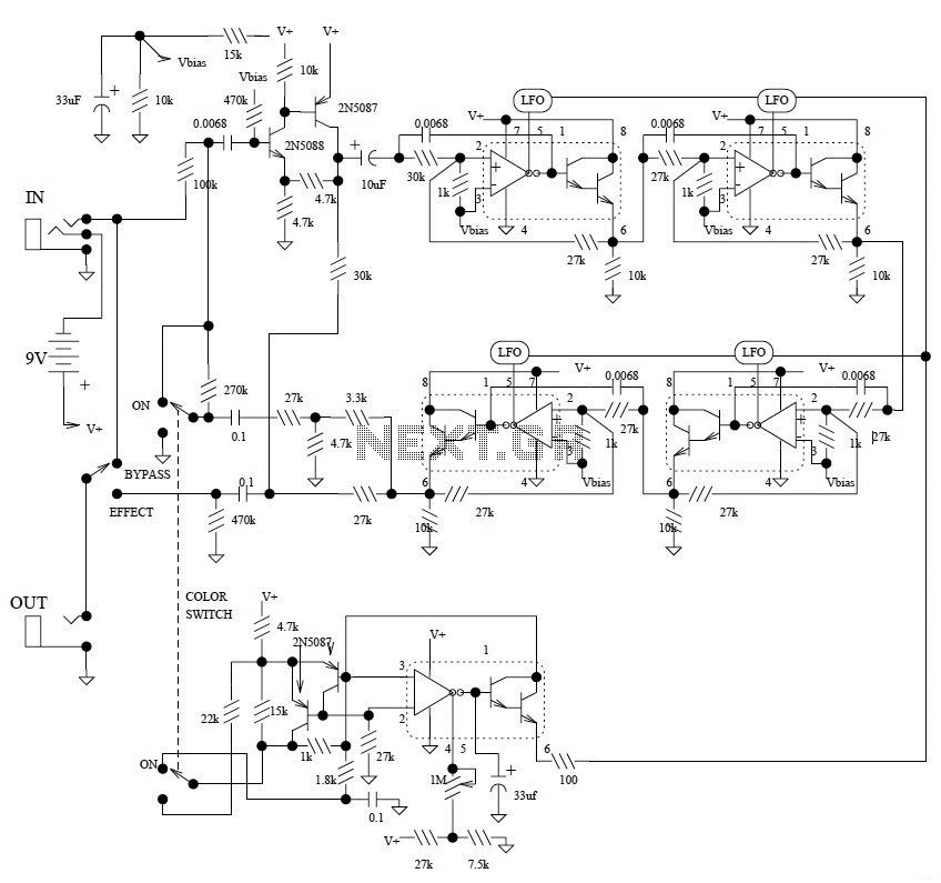
This is the schematic diagram of the Electro-Harmonix Small Stone Phaser guitar effect pedal. The Small Stone is notable for using Operational Transconductance Amplifiers (OTAs) for phase shift stages instead of traditional operational amplifiers. The Electro-Harmonix Small Stone Phaser is...