
68HC11 as a Digital Timer
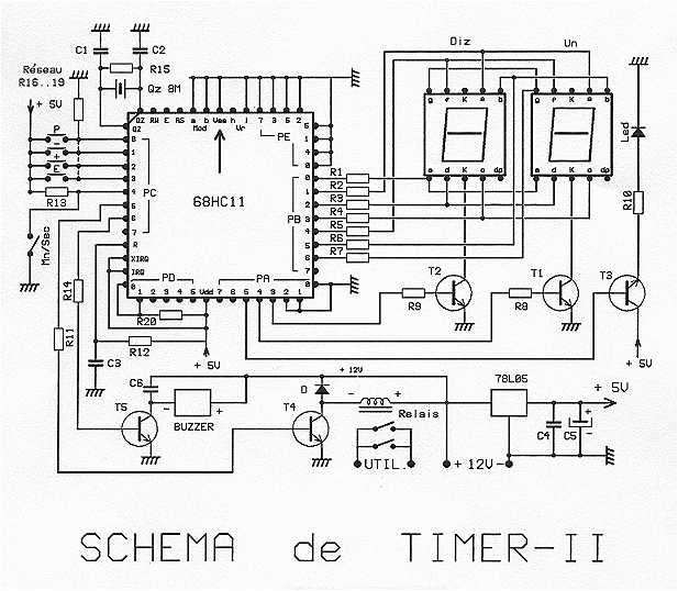
The timer circuit operates effectively as a programmable timer controller for external loads rated at 8A and 380V. At the heart of the circuit is the 68HC11 microcontroller, which is clocked by an 8 MHz crystal oscillator, providing precise timing capabilities for programmable durations ranging from 0 to 99 seconds and 0 to 99 minutes. The user interface consists of a 4-button keypad that allows the user to set the desired time and also displays the elapsed time on multiplexed LED displays.
The multiplexing of the displays is managed through Port B of the microcontroller, utilizing a 390-ohm resistor to limit current to the segments. The common cathodes of the displays are controlled by transistors T1 and T2, which are activated by the PA3 lines. An LED connected to line PA5 indicates the operational status of the timer, blinking during the countdown phase.
Input management is handled through Port C, where lines PC0 to PC4 are connected to the keypad. The keys allow users to select between minutes and seconds, while PC5 to PC7 control the relay and buzzer via transistors T4 and T5, respectively. The microcontroller is reset using a combination of resistor R12 and capacitor C3, ensuring stable startup conditions.
Power for the entire circuit is supplied externally at 12V DC, which can be sourced from a battery or power adapter. The microcontroller and displays require a regulated 5V, provided by a 78L05 voltage regulator. The design incorporates various resistors and capacitors to ensure reliable operation, including a tantalum capacitor for stable power supply filtering.
The assembly process is straightforward, following a specific order to ensure proper placement of components on the printed circuit board (PCB). The resistors, capacitors, transistors, and connectors must be soldered correctly, and the final assembly includes the relay and buzzer.
During commissioning, the circuit should be powered to verify the presence of the correct voltage levels before placing the microcontroller and displays. Once operational, users can initiate the countdown by selecting the desired time and pressing the appropriate buttons to adjust the timer settings. The system provides feedback through the LED indicator and sounds an alert via the buzzer once the countdown reaches zero.
This timer circuit is designed to be both practical and user-friendly, making it suitable for various applications requiring precise timing and control of external loads.The timer is proposed an effective model for controlling an external load 8A/380V. Equipped with a 68HC11 mu.P associated with an 8 MHz crystal, it can get very precise programmable durations. Two lines are planned: from 0 to 99 seconds and from 0 to 99 minutes. Both displays allow programming in conjunction with a 4-button keypad. They also display the count of elapsed time. The relay output double contact work controls the external load. The choice is enabled by 68HC11A1FN lequartz 8 MHz and operates in BOOTSTRAP with Moda MODB = = 0. It runs on an internal program residing in the EEPROM. The displays are multiplexed, the attack of the segments being shared and managed by the port B via resistance of 390 W . PA3 PA3 lines and provide the multiplexing transistors T1 and T2 controlling the common cathodes of the displays.
Line PA5 blink a LED diode in the range "min" to show that the counting is done well. The port C lines PC0 to PC4 as inputs, 4 keys on the keyboard connected to the inverter and "min / sec. PC5 to 7 lines are outputs. FP5 control relay via T4 and FP6 the buzzer using T5. Port E is not used. PD0 and PD1 lines are drawn at +5 V for the R20 correct starting the program. The reset mu.P the power is obtained by R12 and C3. Power is supplied by the 12V DC externally obtained either by battery or by a block sector. The relay and the buzzer used that tension. Cons by feeding mu.P and viewers is by bringing the 78L05 5V to 12V classics. 1 68HC11A1FN programmed ( to download the binary program ) Q1 BC549B .. 5 or eq. 1 red LED 5mm 1 1N400x 1 Reg 78L05 R1 .. 7390 W R8 / 9 3.9 k W R10 470 W R11/14 3.9 k W R12 27 k W R13 18 k W R15 1 M W Network 4 .. 19 R16 R 22 k W + 1 common C1 / 3 33 pF in 2.5 REB LCC C3/4/6 0.1 uF R20 22 k W SMD 1206 C5 4.7 fd 16V Tantalum Bead A printed circuit board ( PostScript file of Cimpr ) 4 D6 round keys: 1 br CORD6R PLCC socket 52, CORD6B, 2 displays OPAFFCC CORD6J, CORD6V An 8 MHz quartz preferably low profile 1 buzzer 1 x SOED103 ALE120 1 1 changeover relay RLST212V COSP244 2 sockets CO20054 1 box HAED200GM cut 20 tulip pins (4 x 5) 2 x 10 mm bolts 2 nuts + 2 + 2 x 5 mm spacers 2 MOUNTING You can follow the following order: The resistors R1 to R15 R16-19 network in the right direction, common to the left Strips of pins improves tulip displays The 2 straps The capacitors C1 to C6 The transistors T1 to T5 The PLCC socket well oriented The resistor R20 on the back To place the buttons, the inverter and the LED, we recommend you use the front casing.
Then adjust the position of the 4 buttons so that they protrude slightly. Weld so the inverter and LED (long wire down) Remove and finish welding the relay and diode, then the buzzer whose legs are IN the printed circuit with the spacers. Solder the son on the back. Finally the connector and 12V output sockets, flat on the copper. COMMISSIONING AND USE Before placing 68HC11 and Displays, powered by the 12V ( + on the central pin connector ) and check that everything is normal and that the +5 V is present.
Disconnect and mount mu.P and displays. Power back up: The displays must mark "00" Otherwise cut and CHECK! ! If all goes well, proceed to the use phase: - Set the switch on min or sec Press "P": The display will flash Press "+" to increase or "-" to decrement. Note that we move from 99 to 00 or 00 to 99, which allows to go quickly at the end of the range. Briefly adds or subtracts 1 unit. A longer puts forwards. Press "P" when the desired value is obtained. The blinking stops. Pressing "E" launch phase of countdown time to work with the relay. Position "mn" LED blinks 1 second on, 1 second off. Return to "00", the relay returns to rest and the buzzer sounds Pressing "E" back to the previously set value and stops the buzzer
🔗 External reference
Related Circuits

This circuit features an adjustable output timer that can re-trigger at specified intervals. The output duration can range from a fraction of a second to over half an hour, with the ability to repeat at consistent intervals from seconds...

This circuit features an adjustable output timer capable of re-triggering at specified intervals. The output duration can range from a fraction of a second to over half an hour, and it can be configured to repeat at regular intervals...

The latest circuit diagram of the AD2496 is presented here. All modifications intended and described in the article regarding the prototype have been implemented. Additionally, two current-compensated chokes have been introduced to enhance electromagnetic compatibility (EMC) immunity. While these...

The schematic below illustrates four methods of controlling a relay with a digital logic signal. Figure A can be used in most cases where the relay coil requires 100 mA or less and the input current is 2 milliamps...
Interface the LCD with the 8051 microcontroller AT89S52. However, upon powering up the microcontroller, the LCD displays only black boxes. Multiple codes have been tried, but the output remains the same. The circuit has been simulated in Proteus, where...
The digital counter circuit described utilizes an infrared signal to detect moving targets, making it suitable for counting small devices on a production line as they move along a conveyor belt. This circuit can also be employed for various...