
6V6 6J5 Class A Vacuum Tube (Valve) Amplifier Circuit
The amplifier design showcases a classic approach to audio amplification using vacuum tubes, emphasizing the importance of component selection and layout in minimizing noise and maximizing performance. The choice of the 6V6GT tube highlights its versatility and suitability for audio applications, especially when configured in triode mode to achieve desirable linearity and sound quality. The output transformer’s specification is critical, as it not only facilitates impedance matching but also influences the overall tonal characteristics of the amplifier. The full-wave rectification process employed ensures a stable DC supply, while the linear power supply design contributes to low noise levels, essential for high-fidelity audio reproduction.
In terms of construction, careful attention to the layout and orientation of transformers and wiring is essential to mitigate electromagnetic interference. The strategic placement of the OT and PT, along with the use of twisted pairs for AC wiring, further enhances the amplifier's performance by reducing hum and noise. Overall, this project exemplifies the principles of vacuum tube amplifier design, combining traditional techniques with practical considerations for modern audio applications.This is my first successful vacuum tube project. The output of this small amplifier in which a 6V6GT output pentode is connected as triode is about 4. 5 watts. This project involves a single ended audio amplifier, which consists of a resistive input network, a driver stage, and an output stage to a typical 8 ohm loudspeaker load, all the while, us
ing a minimum of supportive passive components for biasing and coupling duties. Power-supply voltage is provided by full wave diode rectification of 230 VAC by a magnetic transformer. This design provides a quality audio amplifier. The major factor involving the design of this single ended output stage is matching an available output tube to an available output transformer (OT), which can provide the proper impedance matching.
Using typical operating parameters, the 6V6 power tube, operating in triode mode, has an ideal load impedance of 5k Ohm, and generates about 4. 5 watts of power. An OT was used, handling 8 watts and providing impedance matching from a 5k primary to an 8 ohm secondary, which is a common loudspeaker impedance.
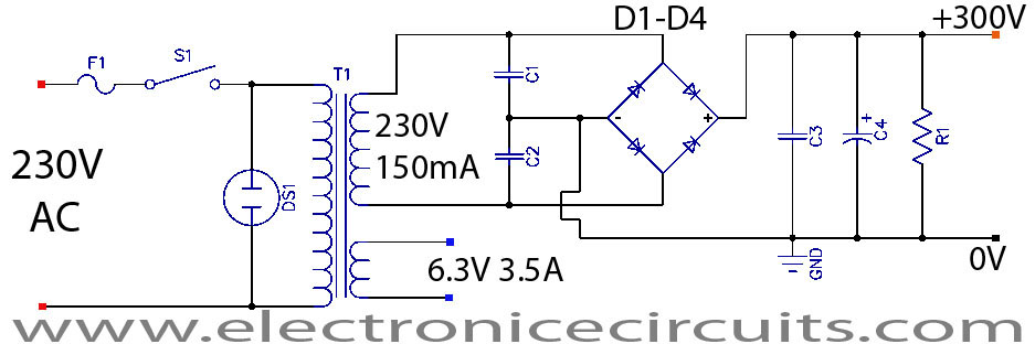
The amplifier uses a simple linear power supply to develop 300VDC. Heater voltages are supplied directly from the 6. 3VAC taps on the secondary of the power transformer. The other secondary windings, rated at 230VAC are used for the DC supply. It consists of a 4 rectifiers, variety of smoothing capacitors and resistor. Several construction issues were considered in the building of this amplifier. High power supply voltages, large and leaky inductive components, and high temperatures are among these considerations. I used old tube amplifier chassis. Magnetic flux is expelled from the transformers as shown by the red arrows above. By placing the output transformer (OT) and power transformer (PT) at opposite ends of the chassis, and rotating their axes 90 ° from one another, induction noise from PT to OT is reduced.
Although this configuration sees flux from the OT directed at the 6V6, OT flux interference into the sensitive preamp stage tube is avoided. Beneath the chassis hum reduction is further achieved by winding all pairs of wire containing AC (filament heater wires, PT primary, and secondary wiring to the diode rectifier).
🔗 External reference
Related Circuits
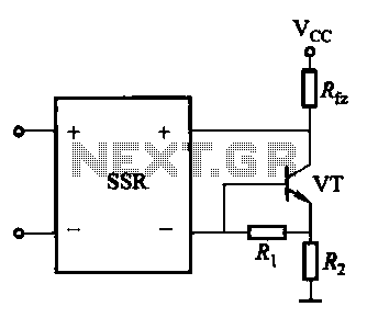
A DC solid-state relay (DC-SSR) driving a high-power load circuit is illustrated in (a) below; the high-power load driving circuit is depicted in (b) below. The DC solid-state relay (DC-SSR) serves as a crucial component in controlling high-power loads, providing...

This straightforward design of an inverter circuit is capable of delivering high output power with an efficiency of approximately 75%. It provides guidance on constructing an inverter that can meet most power requirements at a reasonable cost. The article...

A simple 16-volt switching power supply circuit can be constructed using the provided diagram, which is based on the MAX668 constant-frequency, pulse-width modulating (PWM), current-mode DC-DC controller. This integrated circuit is designed for a wide range of DC-DC conversion...
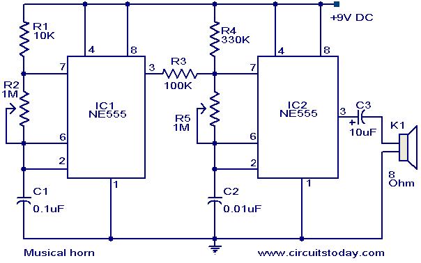
This document outlines a straightforward circuit diagram for a musical horn utilizing two NE555 integrated circuits (ICs). Both ICs are configured as astable multivibrators. The output from the first multivibrator is connected to the discharge pin (pin 7) of...
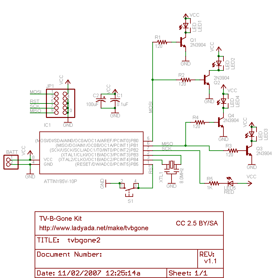
Why use one resistor and one transistor for each LED instead of connecting the LEDs in series and controlling them with a single transistor? This approach is controlled by an Arduino pin through a single resistor. While there is...
In a grid-driven amplifier, it is essential to match the low impedance of the driving transmitter (typically 50 ohms) to the high impedance input of the tube (usually several thousand to several million ohms). The signal from the input...