
7-segment display
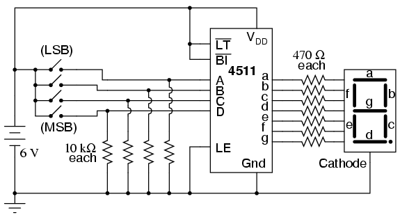
The circuit utilizes the 4511 display driver IC, which is integral for driving a common-cathode 7-segment display. The BCD inputs (A, B, C, D) are connected to four switches that allow for binary input from 0000 to 1111. Each output (a-g) from the 4511 is connected to the corresponding segments of the 7-segment display through a series of 470-ohm resistors to limit the current and prevent damage to the LEDs. The common-cathode configuration of the display means that all cathodes of the segments are tied together and connected to ground, while the anodes are driven by the outputs of the 4511.
The experiment includes the functionality of the three additional inputs: "Lamp Test," "Blanking Input," and "Latch Enable." The "Lamp Test" allows for testing all segments of the display by setting the input low, illuminating all segments. The "Blanking Input" can be used to turn off the display when set low, while the "Latch Enable" input, when set high, allows the current BCD input to be latched, maintaining the display state regardless of changes to the BCD inputs.
To facilitate experimentation, jumpers are used to connect these inputs to either Vdd or ground. By manipulating these inputs, users can observe the effects on the display and gain a deeper understanding of how the 4511 IC operates in conjunction with the 7-segment display. The datasheet for the 4511 provides critical information on the behavior of the IC under various conditions, making it a valuable resource for understanding the operation of the circuit.This experiment is more of an introduction to the 4511 decoder/display driver IC than it is a lesson in how to "build up" a digital function from lower-level components. Since 7-segment displays are very common components of digital devices, it is good to be familiar with the "driving" circuits behind them, and the 4511 is a good example of a typi
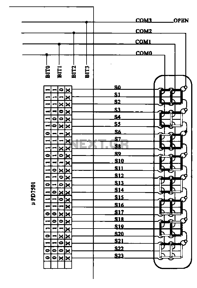
cal driver IC. Its operating principle is to input a four-bit BCD (Binary-Coded Decimal) value, and energize the proper output lines to form the corresponding decimal digit on the 7-segment LED display. The BCD inputs are designated A, B, C, and D in order from least-significant to most-significant. Outputs are labeled a, b, c, d, e, f, and g, each letter corresponding to a standardized segment designation for 7-segment displays.
Of course, since each LED segment requires its own dropping resistor, we must use seven 470 © resistors placed in series between the 4511`s output terminals and the corresponding terminals of the display unit. Most 7-segment displays also provide for a decimal point (sometimes two!), a separate LED and terminal designated for its operation.
All LEDs inside the display unit are made common to each other on one side, either cathode or anode. The 4511 display driver IC requires a common-cathode 7-segment display unit, and so that is what is used here. After building the circuit and applying power, operate the four switches in a binary counting sequence (0000 to 1111), noting the 7-segment display.
A 0000 input should result in a decimal "0" display, a 0001 input should result in a decimal "1" display, and so on through 1001 (decimal "9"). What happens for the binary numbers 1010 (10) through 1111 (15) Read the datasheet on the 4511 IC and see what the manufacturer specifies for operation above an input value of 9.
In the BCD code, there is no real meaning for 1010, 1011, 1100, 1101, 1110, or 1111. These are binary values beyond the range of a single decimal digit, and so have no function in a BCD system. The 4511 IC is built to recognize this, and output (or not output!) accordingly. Three inputs on the 4511 chip have been permanently connected to either Vdd or ground: the "Lamp Test, " "Blanking Input, " and "Latch Enable.
" To learn what these inputs do, remove the short jumpers connecting them to either power supply rail (one at a time!), and replace the short jumper with a longer one that can reach the other power supply rail. For example, remove the short jumper connecting the "Latch Enable" input (pin #5) to ground, and replace it with a long jumper wire that can reach all the way to the Vdd power supply rail.
Experiment with making this input "high" and "low, " observing the results on the 7-segment display as you alter the BCD code with the four input switches. After you`ve learned what the input`s function is, connect it to the power supply rail enabling normal operation, and proceed to experiment with the next input (either "Lamp Test" or "Blanking Input").
Once again, the manufacturer`s datasheet will be informative as to the purpose of each of these three inputs. Note that the "Lamp Test" (LT) and "Blanking Input" (BI) input labels are written with boolean complementation bars over the abbreviations.
Bar symbols designate these inputs as active-low, meaning that you must make each one "low" in order to invoke its particular function. Making an active-low input "high" places that particular input into a "passive" state where its function will not be invoked.
Conversely, the "Latch Enable" (LE) input has no complementation bar written over its abbreviation, and correspondingly it is shown connected to ground ("low") in the schematic so as to not invoke that function. The "Latch Enable" input is an active-high input, which means it must be made "high" (connected to Vdd) in order to invoke its function.
🔗 External reference
Related Circuits
This document outlines the theory behind a high-speed control scheme for an LED display screen circuit. The circuit utilizes the MCS51 series microcontroller to manage the LED display. A 62512 random access memory (RAM) is employed for data storage,...
A scoreboard is located in the center of the room, which will be controlled from backstage. The scoreboard features two individual 3-digit numbers. Whenever the score changes, a sound will be emitted. The simplest, most efficient, and cost-effective solution...
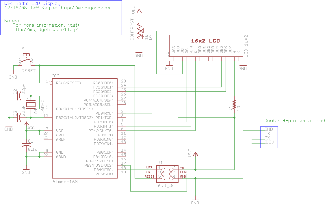
This is the seventh part of an ongoing series about building a low-cost, open-source streaming internet radio. If you have not already, check out the previous parts for some background about the project. In part six, UNIX-style shell commands...
Examples of the structure of several liquid crystal display drive circuit CPU tubes. Liquid crystal display (LCD) drive circuits play a critical role in controlling the operation of LCD panels, which are widely used in various electronic devices. These circuits...
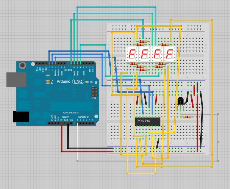
The intention is to utilize this code in future projects involving 7-segment displays. For those interested in learning more about 7-segment displays, additional information can be found in a related post. 7-segment displays are widely used in electronic devices for...
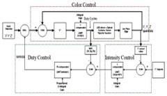
The system utilizes RGB LED light sources, an optical sensor, and a feedback controller. The purpose of employing optical feedback is to ensure color stability over temperature variations, maintain constant brightness, and control any specific color point or brightness...
Warning: include(partials/cookie-banner.php): Failed to open stream: Permission denied in /var/www/html/nextgr/view-circuit.php on line 713
Warning: include(): Failed opening 'partials/cookie-banner.php' for inclusion (include_path='.:/usr/share/php') in /var/www/html/nextgr/view-circuit.php on line 713