
7-segment display counter
The schematic for this project will include a 7-segment display, a binary counter IC (such as the 4511), and a timing element, typically a 555 timer configured in astable mode to generate a one-second pulse. The output of the timer will trigger the counter to increment its value, which in turn will drive the 7-segment display. The binary outputs from the counter will connect to the inputs of the display driver IC, which will convert the binary values to the appropriate segment activations.
In the case of the TFK214 common cathode display, the anodes of each segment will connect to the corresponding output pins of the 4511 driver, while the common cathode pin will be connected to ground. This configuration allows for the segments to be illuminated based on the binary output of the counter.
Additionally, the circuit may include a push-button switch for user interaction, enabling the reset of the counter or starting the reaction-time game. The entire assembly can be laid out on a breadboard for prototyping, ensuring that all connections are secure and correctly oriented. Testing should be conducted to verify that each segment lights up as expected and that the counter increments accurately with each pulse from the timer. Proper documentation of the pin configuration and circuit behavior will facilitate troubleshooting and future enhancements to the design.This project introduces a fundamental electronics building block: the counter. Building yourself a simple circuit which increments display count every second, you are going to learn how displays work and how to drive them in the right way. For those who already know how to drive display and counters, we suggest to skip this section and jump to th
e second part of the article, which uses a counter to implement a reaction-time game. A 7 segment display is manufactured encapsulating 7 LEDs inside a single case. Each LED is given a shape and position which makes it a separate "segment": lighting teo or more segment in different patterns, we can read all digits from 0 to 9 on the display. Segmenfs are conventionally identified with letters from A to G. The schematic diagram above shows the correspondence between segment position and the letter. For example, number 2 is obtained lighting segments A, B, G, E, D, whereas number 3 requires segments A, B, C, D, G.
If all seven segments are lit then a number 8 is obtained. Despite of its name, practically all modern 7-segment displays contain 8 LEDs! This eitghth segment is required for the decimal point, and it is conventionally labelled "H" or "DP". To reduce pin count from 16 to 9, almost all 7-segment displays connect together one pin from all of the internal LEDs bringing it to a single display pin.
In the case of so called "common cathode" displays, all cathodes are connected together and to the common cathode pin, while the anodes are connected to segment pins indifdually. The opposite for "common anode" displays. The TFK214 display we selected for this projects is a common cathode 7-segment display. The catodhes are connected to pin 3, with anodes of segments A, B, C, D, E, F, G, H to the remaining pins.
Pin 6 is connected to the common cathode as well; you need to connect only one to the negative supply. You can try to light any segment up as you do with any other LED. The prototype can be assembled on a solderless breadboard. The circuit is not a difficult one, but special care is required in order to complete all the connections.
Also, be careful not to reverse any of the polarized parts (display, Nutchip, 4511). You can replace the TFK214 with any other common cathode display: should you use an equivalent, double check the pinout as it may differ from the TFK214. A quick check can be performed using a 1000 ohm resitor and a 5 volt power source. Connect the resistor in series with the positive rail; then connect the negative rail to the pin supposed to be the common cathode, Next, touch the other pins with the free lead of the resistor.
Each time you touch a new pin, a new segment should turn on. If none of the segments lights up, chances are that the negative rail is connected to a pin other than the negative rail. Try different pins until some segments lights up. Repeat this procedure until all of the pins are discovered, taking note for future reference. Note also that some display have more than one pin connected to the common cathode. If your display pinout matches the one for TFK214, you can use the following picture as a guide, otherwise fit the resistors in orders to suit the display`s pinout: The truth table for the counter is very simple.
It`s as simple as letting the outputs take the binary values corresponding to the numbers from 0 to 9, changing state sequentially each and every second. You can find the binary values to be assigned to the outputs from the 4511` truth table. Enter these values to the states st00 to st09, but there is a trick: as Nutchips require the output 1 to be written on the leftmost position, opposed to the usual way of writing binary numbers.
This is why the outputs appear mirrored in the truth table: e. g. the number 3 is 0011 in binary, nad is written as 1100 in the truth table. Can you imagine how to use the circuit in order to build a reaction time game You should add a pushbu 🔗 External reference
Related Circuits

The interface circuit is placed between the computer's standard video signal output terminal and the television. It amplifies the standard 1V (Peak-to-Peak) video signal to 3V (Peak-to-Peak). The negative feedback circuit consists of transistors T1 and T2, providing a...

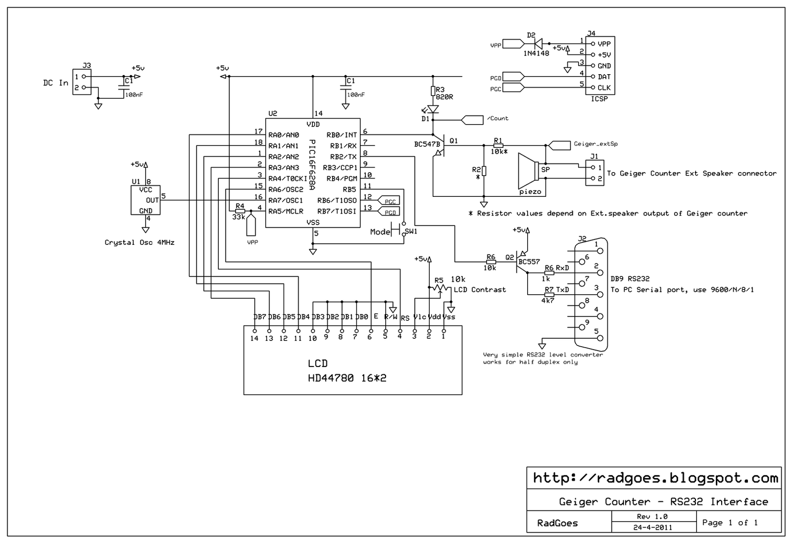
One of the most unfortunate features of the typical portable Geiger counter is the short lifespan of the costly high-voltage batteries. The limitation of high-voltage battery life in portable Geiger counters significantly affects their usability and operational efficiency. These devices...
This circuit utilizes a synthesized sound chip from Holtek, the HT-2811, which produces the sound of a "ding-dong" chiming doorbell. Additionally, it incorporates a CMOS 4026 counter display driver integrated circuit (IC) to tally the number of visitors. The...
A selection of reasonably priced ex-army radiation detectors was discovered at an army surplus store. Among them was a Frieseke & Hoepfner FH40T Geiger counter, equipped with a FHZ76V energy-compensated Geiger-Mueller tube, which is sensitive to gamma (³) and...

A simple frequency meter or frequency counter circuit featuring an LCD display and an AVR microcontroller. This includes a DIY schematic circuit diagram and embedded C code. The frequency meter circuit is designed to measure the frequency of input signals...
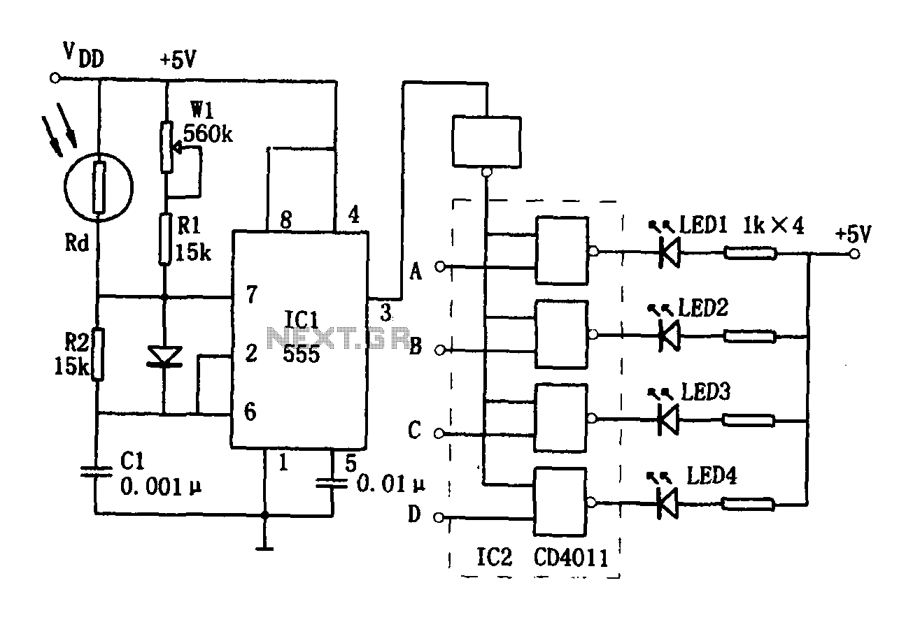
The brightness display circuit consists of a light-sensitive sensor, an oscillation circuit, and an LED display circuit. The light-sensitive sensor is a photosensitive resistor (Rd). The multivibrator is composed of Rd, R1, W1, R2, and C1, along with a...
Warning: include(partials/cookie-banner.php): Failed to open stream: Permission denied in /var/www/html/nextgr/view-circuit.php on line 713
Warning: include(): Failed opening 'partials/cookie-banner.php' for inclusion (include_path='.:/usr/share/php') in /var/www/html/nextgr/view-circuit.php on line 713