
8 Channel LPT Relay Circuit

The circuit design incorporates a Power Battery Terminal (PBT) to streamline the connection of relays and auxiliary power sources, enhancing the overall functionality and ease of use. Each relay channel is equipped with an LED indicator that visually represents the operational status of the relay, allowing for quick diagnostics and monitoring.
The use of Berg pins for power and trigger voltage connections simplifies the wiring process, enabling users to efficiently connect and disconnect components as needed. This modular approach not only improves the reliability of the connections but also facilitates maintenance and troubleshooting.
The relay output can be utilized for various applications, including controlling high-power devices or interfacing with other electronic systems. The design ensures that the relays are activated only when the appropriate trigger voltage is applied, thereby protecting the circuit from accidental activation.
Overall, this circuit exemplifies a practical solution for managing relay outputs and auxiliary power connections, making it suitable for a wide range of electronic projects and applications.This circuit is using Power Battery Terminal (PBT) for easy relay output and aux power connection. The LED on each channel indicates relay status. Berg pins for connecting power and trigger voltage. 🔗 External reference
Related Circuits

This LM723 variable power supply circuit design is a straightforward variable power supply capable of delivering an output voltage ranging from 8 to 30 volts, with a maximum output current of 3 amperes. The circuit features a low output...

A simple preamplifier circuit is often required, utilizing a few components for ease of construction. This circuit employs an operational amplifier, specifically the Motorola TCA5550, which features a dual amplifier configuration. It provides outputs for adjusting volume, balance, treble,...

The TDA6106Q test circuit, as depicted in the provided figure, operates with a feedback factor of 1/116. The input signal, Vin, is received from the input network consisting of resistors R1, R9 and capacitors C1, C2. The TDA6106Q IC...
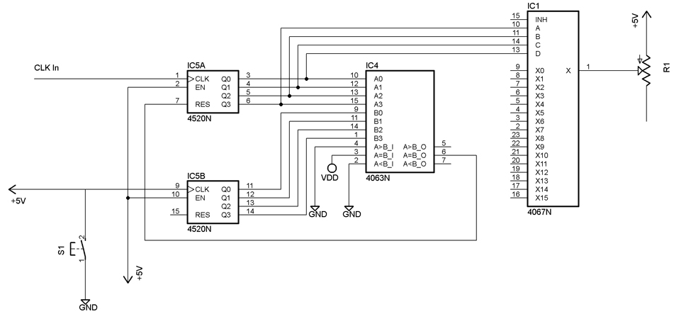
The following video showcases a test circuit of a 16-step analog sequencer based on Mauno Tuominen's schematic for an analog CMOS sequencer utilizing a 4067N multiplexer/demultiplexer. A DIY version of the sequencer can be found at studiomanus.com. An old...
The IR Jammer is a fun project that provides a bit of safe, non-destructive fun. The Infrared Remote Control Jammer allows you to render all IR remote controls inoperative! The microcontroller in this design allows for all 6 of...

A simple 5-volt switching power supply electronic circuit project can be designed using the FAN302HL, a highly integrated PWM controller integrated circuit. This IC provides several features that enhance the performance of general flyback converters. The constant-current control of...