
8 channel thermocouple based temperature data logger
The proposed circuit utilizes eight MAX6675 integrated circuits, interfaced with a microcontroller to measure temperatures from thermocouples. Each MAX6675 provides a digital output corresponding to the temperature detected by its thermocouple input. The SPI communication protocol simplifies the connection, allowing multiple devices to share a single clock line while maintaining separate data lines for odd and even devices. The NCS lines, which activate the respective MAX6675 chips, are grouped in pairs to minimize the number of control lines needed, effectively optimizing the wiring complexity.
The microcontroller, potentially a PIC16F877, will manage the SPI communication, enabling the reading of temperature data from each MAX6675 in a sequential manner. The microcontroller's firmware will need to be programmed to handle the timing of the SPI transactions, ensuring that each chip is selected and read in turn. The data collected can be processed and displayed, or transmitted via a serial port to a PC for further analysis.
Power supply considerations are crucial, particularly for maintaining the integrity of the thermocouple readings, as noise can significantly affect the accuracy. The design should incorporate appropriate filtering and possibly shielding to mitigate electromagnetic interference, especially if high power devices are present in the same environment.
The ADC functionality is essential for converting the analog signals from the thermocouples into digital data that the microcontroller can interpret. The selection of a 12-bit ADC provides a balance between resolution and noise susceptibility, though careful PCB layout will be necessary to ensure that the analog signals remain clean.
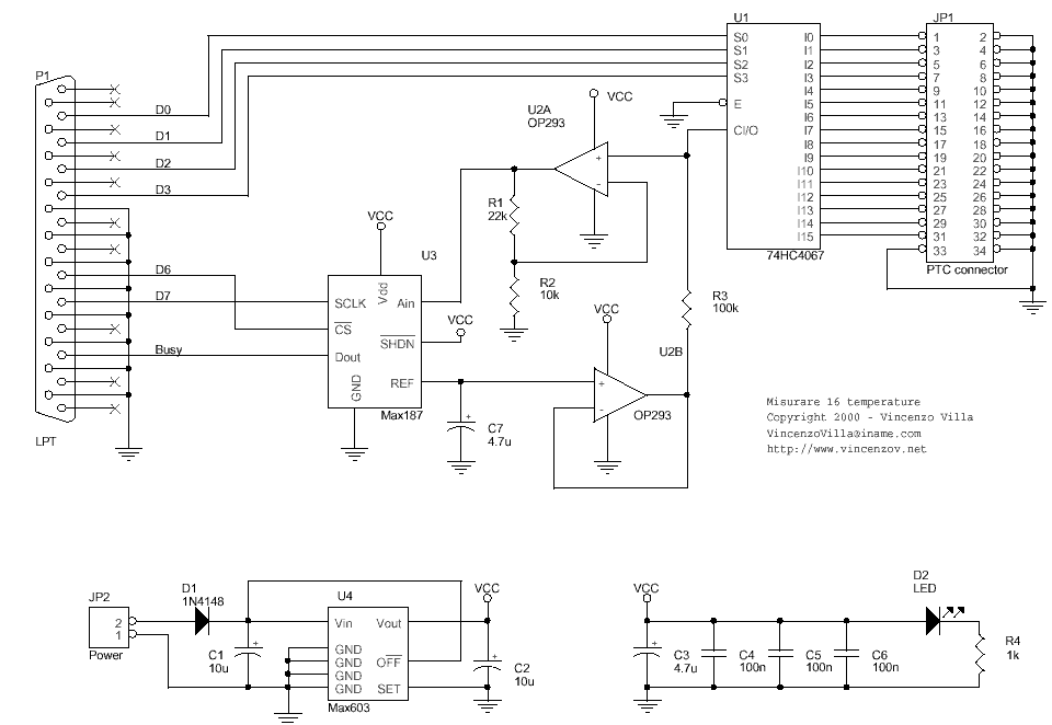
In summary, the circuit design integrates multiple MAX6675 ICs in a configuration that maximizes efficiency while addressing the challenges of noise and accuracy inherent in thermocouple measurements. The resulting system is capable of logging temperature data effectively for various applications, including industrial monitoring and high-performance automotive diagnostics.You need to wire 8 Max6675 ics to a microcontroller. You can parallel all the clock inputs. The NCS lines of numbers 1 and 2, 3 and 4 etc can be connected together. The SO lines of all the odd numbered Max6675 can be connected together, as can the even ones. That way you can read 8 temperatures on 7 wires (1 clock, 2 data and 4 not chip select) the first is a simple 8 channels / 12 bit ADC connected to the parallel port of a personal computer that is able to measure eight voltage and to transfer them to a PC. The second is the schematic for a 16 channel Temperature data logger but how you can see he is using a MAX 187 that i dont think is good for my temperature goal.
and both send the captured data to a pc with a serial port Actually the MAX6675 that Diver300 suggested would appear to work like a charm, SPI is not a tough bus to work with and you can plunk an SPI EEPROM like the 25LC256 no problem. Here`s the rub, if you know what your doing it could be done in 10 days but that`s if you`ve already got the parts and the design started.
You still have to program and debug any working design. As with all thermocouple circuits, the voltage on the thermocouple is tiny and noise can be a problem. I had some problems getting rid of noise, (I can`t remember the details) but it was on a board switching 10A at 230V ac.
If it`s not for school and if it`s not for hobby (who need`s +1000 °C in his living room) then it`s for industry. Then ther`s only one way to do it in 10 days; order one of these: the first is a simple 8 channels / 12 bit ADC connected to the parallel port of a personal computer that is able to measure eight voltage and to transfer them to a PC.
The second is the schematic for a 16 channel Temperature data logger but how you can see he is using a MAX 187 that i dont think is good for my temperature goal. and both send the captured data to a pc with a serial port How many samples do you need to capture, over what time Is it AC or battery What probes are you going to use Do you need a display in the design or a keypad, what enviroment will this device be used in What size are you hoping for Something like a PIC16F877 should do the job nicely, and EPE did an 877 datalogger project years back, you just need to make the opamp thermocouple circuits.
How many samples do you need to capture, over what time Is it AC or battery What probes are you going to use Do you need a display in the design or a keypad, what enviroment will this device be used in What size are you hoping for This converter resolves temperatures to 0. 25 °C, allows readings as high as +1024 °C, and exhibits thermocouple accuracy of 8LSBs for temperatures ranging from 0 °C to +700 °C.
i m gonna use the probe showed in this web site and actually the data logger in this site is pretty much what i want to build but 8 channels. Like I said before, it`s 8 channel but 10 bit - however, 10 bit is probably more than enough, with 12 bit the extra resolution is likely to be lost in noise anyway, and requires very careful PCB layout.
You can use the Magenta kit if you have a temperature to voltage converter. Be aware that you need at least 1. 22mV accuracy. So like Nigel already said, it will require very careful PCB layout. About the probe, they say 0. 1 resolution in a -328 to 2498 range, to achieve that you need at least 15 bit resolution. I think they use standard 16 bit ADC`s 1000/s is correct. have you ever log the temperature that coming out of a dragster muffler or a NASCAR race car this cars use nitro-methane where there s detonations and temperature shock (extremely rapid changes in temperature). I have already the thermocouple probes that are inserted into the header pipe to measure the temperature of the exhaust gas as it e
🔗 External reference
Related Circuits
This document serves as a continuation of the previous work on PWM controllers utilizing 555 timers. The new design incorporates microcontrollers and MOSFETs in place of the 555 integrated circuits and transistors. Two versions have been developed: one equipped...
This inverter circuit can provide a stable 230V output voltage. The operating frequency is determined by a variable resistor (VR1) and is typically set to 60 Hz. Various off-the-shelf transformers can be utilized, or custom-wound transformers can be created...
This two-part article explains the utilization of a simple voltage divider circuit incorporating a thermistor to obtain high-accuracy temperature readings across a wide range of measurements. The first part focuses on the circuit design and explores various methods for...
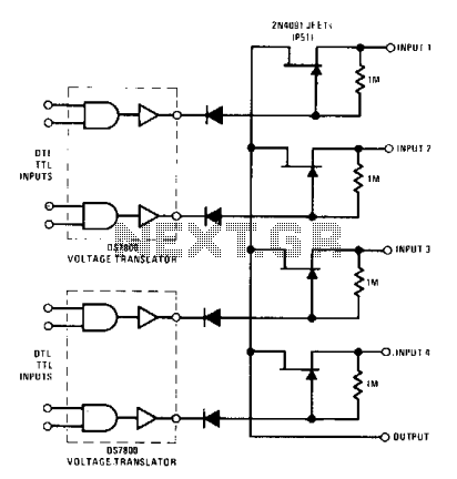
The DS7800 voltage translator is a monolithic device that provides a gate drive voltage ranging from 10 V to -20 V for JFETs while simultaneously ensuring DTL/TTL logic compatibility. This 4-channel commutator utilizes the 2N4091 to achieve a low...
The circuit for the Digital Tachometer/RPM Counter consists of only a few devices. Wire them up according to the following circuit diagram. The PIC used is on a demonstration board, which means the clock, power, and ground pins are...
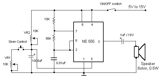
The circuit diagram of an electronic siren based on the NE555 timer produces a sound similar to that of a factory siren. The NE555 timer IC functions as an astable multivibrator with a center frequency of approximately 300 Hz....