
8 Led Audio VU Meter
The audio level meter circuit employs two LM324 quad op-amps configured as a comparator to detect varying audio levels. The circuit is designed to illuminate a series of eight LEDs, each corresponding to a different range of audio signal levels. The LM324 is chosen for its versatility and availability, making it a suitable choice for various audio applications.
In operation, the audio input signal is fed into the non-inverting inputs of the op-amps. Each op-amp is connected to a reference voltage set by a voltage divider, which is typically derived from the circuit's power supply. The output of each op-amp drives a corresponding LED through current-limiting resistors, which in this case are specified as 1K ohms. These resistors are critical in determining the threshold levels at which the LEDs will activate.
The choice of 1K resistors allows for a balanced response across the audio levels, ensuring that each LED lights up at progressively higher input signals. If higher resistance values, such as 5K ohms or more, are used, the circuit's sensitivity may diminish, potentially preventing some LEDs from activating, particularly at lower audio levels.
The op-amps' gain settings can be adjusted to fine-tune the circuit's response to the audio signal, allowing for customization based on specific application requirements. For enhanced performance, bypass capacitors may be added to the power supply pins of the op-amps to mitigate noise and improve stability.
This audio level meter circuit can be utilized in various applications, including audio mixing consoles, sound level monitoring, and visual sound representation in musical equipment. The simplicity and effectiveness of this design make it a popular choice for both hobbyists and professionals in the audio engineering field.This circuit uses two quad op-amps to form an eight LED audio level meter. The op-amp used in this particular circuit is the LM324. It is a popular IC and should be available from many parts stores. The 1K resistors in the circuit are essential so that the LED`s turn on at different audio levels. There is no reason why you can`t change these resistors, although anything above 5K may cause some of the LED`s to never switch on. This circ 🔗 External reference
Related Circuits
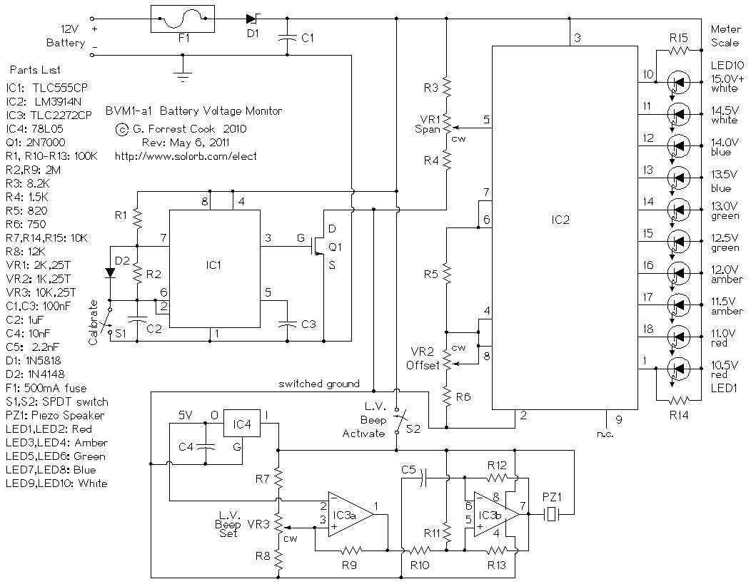
This is a low power voltmeter circuit that can be used with alternative energy systems that run on 12 and 24 volt batteries. The voltmeter is an expanded scale type that indicates small voltage steps over the 10 to...
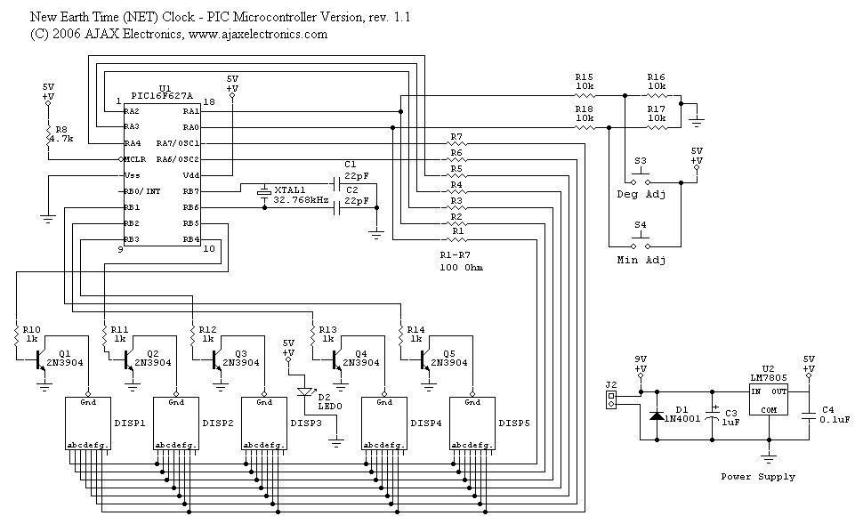
The schematic diagram and electronic assembly are relatively simple, as most of the functionality is managed by the microcontroller code. The schematic diagram serves as a visual representation of the electronic circuit, outlining the connections between various components such as...
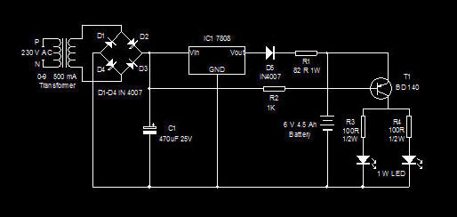
This is a high-efficiency emergency lamp that utilizes high-brightness white LEDs. It automatically activates during power failures and deactivates when power is restored. The emergency lamp circuit is designed to provide reliable illumination during power outages, utilizing high-brightness white LEDs...
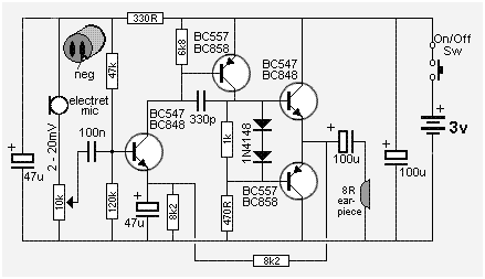
The following circuit presents a Mini Audio Amplifier Circuit Schematic Diagram. Features include a power consumption of less than 3mA, a small output, and the use of a push-pull configuration. The Mini Audio Amplifier Circuit is designed to amplify low-level...
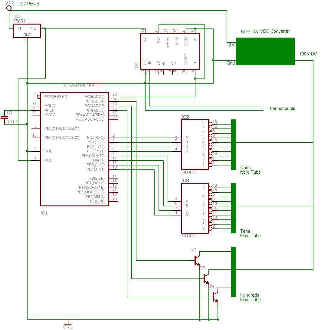
the entire circuit is comprised of integrated circuits. This makes for some easy organization when it goes to the circuit board for soldering. In addition, I used only 3 of the pins on the 3rd nixie tube for the...
The LED flasher circuit operates by flashing an LED using only a 1.5-volt power supply. Typically, a power supply of more than 2 volts is required for an LED to function. The LED flasher circuit designed for operation at 1.5...
Warning: include(partials/cookie-banner.php): Failed to open stream: Permission denied in /var/www/html/nextgr/view-circuit.php on line 713
Warning: include(): Failed opening 'partials/cookie-banner.php' for inclusion (include_path='.:/usr/share/php') in /var/www/html/nextgr/view-circuit.php on line 713