
8 Watt Audio amplifier using LM383
The LM383 audio amplifier circuit is designed to deliver up to 8 watts of output power, making it suitable for small audio applications. The amplifier utilizes a few key components for its operation. The 10µF electrolytic capacitor (C1) is typically used for coupling or decoupling purposes, ensuring that the DC bias does not affect the audio signal. The 470µF electrolytic capacitor (C2) serves as a power supply filter capacitor, smoothing out any fluctuations in the power supply voltage to maintain a stable output. The 0.1µF disc capacitor (C3) is often used for high-frequency bypassing, helping to eliminate noise and ensuring that the amplifier operates efficiently across the audio frequency range.
The LM383 amplifier circuit may include additional components such as resistors and transistors to set gain levels and provide stability. A heat sink may also be necessary to dissipate heat generated during operation, especially when driving speakers at higher volumes. Proper layout and grounding techniques should be employed in the PCB design to minimize noise and interference, which can affect audio quality.
Overall, the LM383 audio amplifier is an excellent choice for hobbyists and engineers looking to build a compact and effective audio amplification solution. Its simplicity and reliability make it a popular choice for various audio applications, from small speakers to personal audio devices.Here is the LM383 schematic for an 8 watt audio amplifier. Very easy to build a mini-audio power amplifier. Part Total Qty. Substitutions C1 1 10uf Electrolytic Capacitor C2 1 470uf Electrolytic Capacitor C3 1 0.1uF Disc Capacit.. 🔗 External reference
Related Circuits
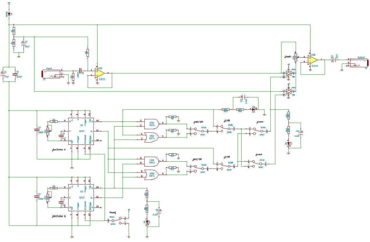
You need to connect pins 1 and 13 of the 4053 to the virtual ground rail (top of C4), not the circuit's 0V rail. The CD4053 is a triple 2-channel analog multiplexer/demultiplexer integrated circuit, widely used for routing analog...
A wide range frequency meter is a useful tool for an electronics lab. This project describes a frequency meter based on the AT90S231 microcontroller that can measure input frequencies up to 50 MHz. The measured frequency is displayed on...
Government data sets available online are often sourced from major metropolitan areas or infrastructural centers. With an easy-to-follow introduction to new software and technologies, the urban sensor kit allows anyone to obtain location-specific information and share it with a...
A lot of friends ask me a circuit AUDIO MIXER, for various uses. I will begin with a circuit which you can it manufacture, as you want. This you can place in the MODULES of inputs any circuit you...
This circuit deactivates an amplifier or other devices when a low-level audio signal at its input is absent for at least 15 minutes. By pressing P1, the device is activated, supplying power to any appliance connected to SK1. The...
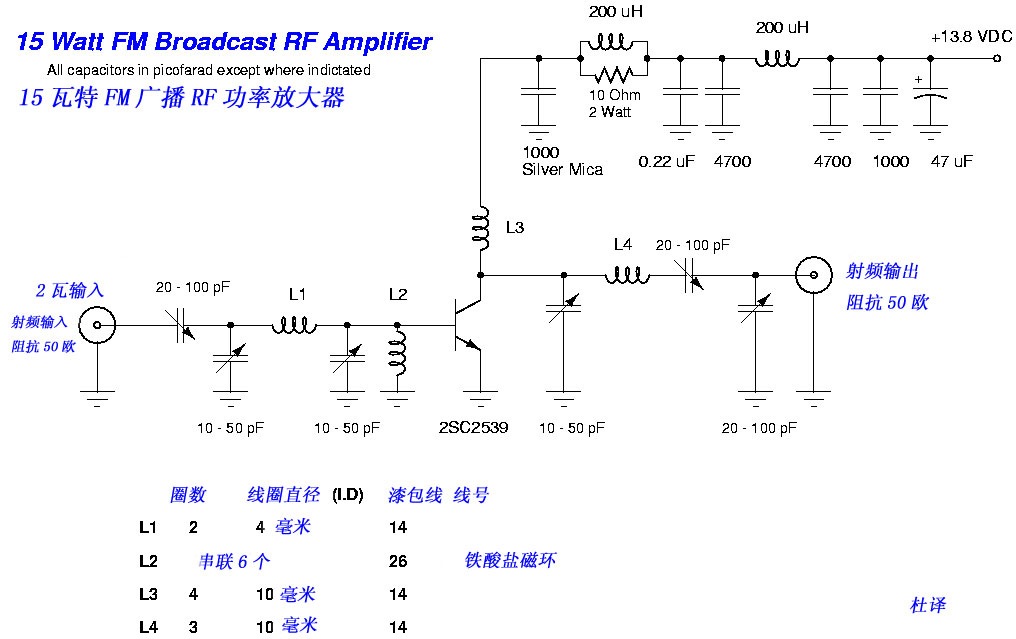
This FM broadcast RF amplifier is constructed using the 2SC2539, which is a silicon NPN epitaxial planar type transistor designed for RF power amplifiers in the VHF band. The FM broadcast RF amplifier utilizing the 2SC2539 transistor operates effectively within...