
8 way electronic selector / switch
Part List
R1-8=10Kohms IC1=74LS374 D1-8=Led 3mm R9=470 ohms IC2=74LS27 C1-3=47nF 63V MKT R10-17= 4.7Kohms IC3=74LS10 RL1-8= 6-12V DC Relay TR1=4.7Kohms Trimmer T1-8=BC550 S1-8=Push button SW
The Elect. Sel. 8 circuit functions as a source selector, utilizing eight independent switches to control eight relays. Each switch (S1 to S8) corresponds to a relay (RL1 to RL8), allowing the user to select one of eight different sources or signals. This setup is particularly useful in applications such as audio systems, where it can be employed to choose between multiple audio inputs, or in digital circuits for selecting various control signals.
The circuit incorporates a series of resistors (R1 to R8 at 10 kΩ and R10 to R17 at 4.7 kΩ) to limit current and protect the components. The inclusion of a 470 Ω resistor (R9) is intended for LED current limiting, ensuring that the 3 mm LEDs (D1 to D8) illuminate without exceeding their maximum current ratings.
The circuit utilizes three integrated circuits (IC1, IC2, and IC3) from the 74LS family, which are known for their low power consumption and high-speed operation. Specifically, IC1 (74LS374) serves as a latch, IC2 (74LS27) functions as a NAND gate, and IC3 (74LS10) acts as a triple 3-input NAND gate. These components work together to manage the state of the relays based on the switch inputs.
Capacitors (C1 to C3) rated at 47 nF and 63V are included for decoupling and stability, ensuring that the circuit operates smoothly without voltage spikes or noise interference.
The relays (RL1 to RL8) operate at a voltage range of 6-12V DC, making them suitable for controlling various loads. The transistors (T1 to T8, BC550) are used as switches to drive the relays, providing the necessary current amplification to activate the relays when a switch is pressed.
A trimmer resistor (TR1 at 4.7 kΩ) is included for calibration purposes, allowing fine-tuning of the circuit's performance. Each switch can be designed to include an LED indicator, providing visual feedback when a particular source is selected.
Overall, the Elect. Sel. 8 circuit is a versatile and efficient solution for source selection in various electronic applications, combining simplicity with functionality. The Elect. Sel. 8 is a simple circuit, with a choice of 8 sources of any sort ,of 8 independent switches. Each switch corresponding with a relay for example the switch S1 activates the RL1 e.t.c. The uses of the circuit are quite a few, choice of entrances in a sound amplifier, choice of command, in a digital circuit etc. In each entrance a LED which may be independent, except if switches with led are used. Part List R1-8=10Kohms IC1=74LS374 D1-8=Led 3mm R9=470 ohms IC2=74LS27 C1-3=47nF 63V MKT R10-17= 4.7Kohms IC3=74LS10 RL1-8= 6-12V DC Relay TR1=4.7Kohms Trimmer T1-8=BC550 S1-8=Push button SW 🔗 External reference
Related Circuits
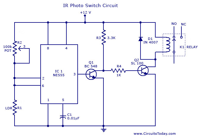
A simple photo switch circuit using the NE555 IC with a diagram and schematic. This photo switch activates a relay when light intensity exceeds a certain threshold. It serves as a light sensor circuit suitable for both home and...
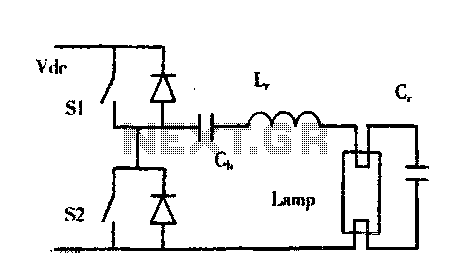
The construction of buildings, when full power is not required, utilizes dimmable electronic ballasts for continuous fluorescent operation, which can further reduce power consumption. Most modern designs and research on electronic ballasts recommend using resonant converter power circuits to...
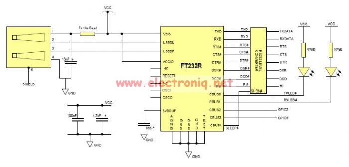
This USB to Serial RS232 adapter is highly beneficial in scenarios where a device with RS232 needs to be connected to a computer lacking an RS232 port but equipped with a USB port. Utilizing the FT232BM chip produced by...
This compact switching power supply utilizes a Schmitt trigger oscillator to control a switching transistor, which delivers current to a small inductor. While the transistor is activated, energy accumulates in the inductor, and upon deactivation, this energy is released...
The 555 timer IC is connected for Astable Operation, the clock pulses are fed to the 4017 IC via the 10K resistor. The 4017 is a 10 stage counter, output 6 (pin 5) is connected to RESET (pin 15),...
This oscillator circuit features a quartz crystal with a nominal resonant frequency of 262,144 Hz, which is cut in an orientation that provides a significant linear coefficient of frequency variation with temperature. In this configuration, the oscillation frequency is...