
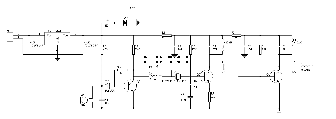
80 mhz 108 mhz fm transmitter circuit
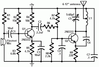
The FM transmitter circuit primarily consists of two 2N2222 transistors, which serve as the main amplification elements. The first transistor (Q1) is responsible for amplifying the audio signals captured from the microphone. The second transistor (Q2) acts as a modulator, mixing the amplified audio signal with the carrier frequency generated by the LC circuit composed of capacitor C5 and inductor L1. The design ensures that the audio signal is superimposed onto the carrier wave, effectively modulating it for transmission.
The LC circuit determines the operating frequency of the transmitter, which is crucial for tuning the device to the desired FM band. The construction of L1 is critical; it should consist of 24 turns of insulated wire wrapped around a cylindrical form, allowing for proper inductance values that enable operation within the specified frequency range of 80 MHz to 108 MHz. The length of the antenna, which should be ideally between 8 to 12 inches, is also essential for efficient transmission and compliance with FCC regulations.
The power supply for the FM transmitter is a 9-volt battery, providing sufficient voltage for the transistors to operate effectively. It is important to ensure that all components are rated appropriately for the voltages and currents involved in the circuit to prevent damage and ensure reliability.
For practical assembly, the circuit layout should be designed to minimize interference and ensure stable operation. Proper grounding and shielding techniques should be employed to prevent signal degradation and maintain the integrity of the transmitted signal. Additionally, the circuit should be tested in a controlled environment to ensure compliance with legal regulations regarding frequency use. Overall, this FM transmitter serves as an excellent educational tool for understanding basic RF transmission concepts and the functioning of transistor amplifiers.FM transmitter or often called fm transmitter uses 2 transistors in this article uses 2 transistors 2n2222. If the fm transmitter is in use voltage supply of 9 volt battery and use an antenna whose length is less than 12 inches, then this fm transmitter will be within FCC limits.
Signals from the microphone in the fm transmitter is reinforced by Q 1, Q2 with carrier frequency generator is determined by the C5 and L1. The frequency of the FM transmitter is in the range 80 MHz - 108 MHz. L1 can be made with as many as 24 e-mail wire wrap and 6 wrap. The following is a picture series for the fm transmitter fm transmitter referred to in article 2 of this transistor. This fm transmitter antenna is connected to the mid point of the antenna length L1 and preferably between 8-12 inches.
FM Transmitter is only used for experiment and learning materials are not to be used for day-to-day, because the use of FM transmitter frequency regulated and protected by law may be understandable. 🔗 External reference
Related Circuits
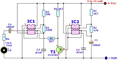
Browse home alarm circuit explanation latest schematic siren wailing with latest Wailing Alarm Siren circuit schematic with explanation. The loudspeaker LS and the resistor marked Rx should be together 75 ohms. If a standard 8-ohm speaker is used, then...
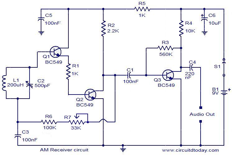
Circuit diagram of a modulator circuit in a transmitter and receiver of amplitude modulation. The modulator circuit in an amplitude modulation (AM) transmitter and receiver plays a crucial role in the process of encoding information onto a carrier wave. In...
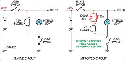
Two headlight reminder circuits are designed for easy installation and operation based on the KISS (Keep It Simple Stupid) principle. The basic circuit consists of a 12V piezo buzzer connected between the lights circuit and a door switch. The...
A wireless hands-free telephone device circuit diagram is presented below. The wireless hands-free telephone device circuit diagram typically comprises several key components that work together to enable hands-free communication. The primary components include a microphone, speaker, Bluetooth module, power supply,...
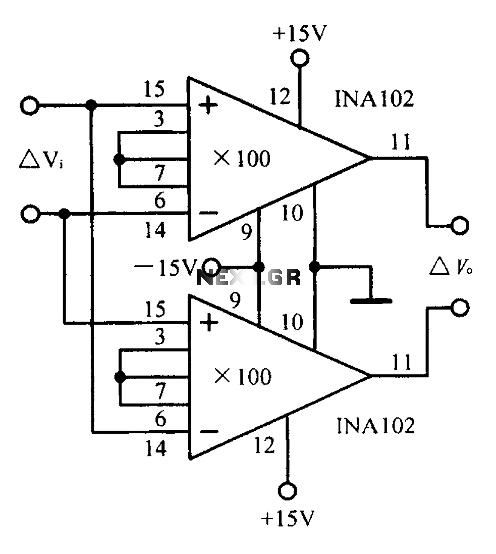
A differential input differential output amplifying circuit diagram. A differential input differential output (DIDO) amplifier is a type of operational amplifier configuration that is designed to amplify the difference between two input signals while rejecting any signals that are common...
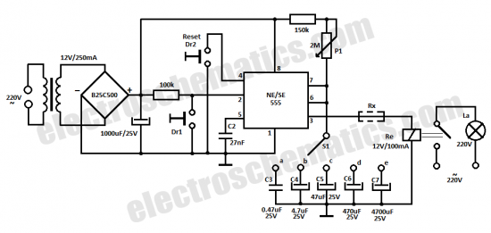
This time delay relay circuit is constructed using the NE/SE555 integrated circuit, manufactured by Intersil, which incorporates a precision timer. The circuit exhibits stability against temperature variations of 0.00. The NE/SE555 timer IC is a versatile device widely used in...
Warning: include(partials/cookie-banner.php): Failed to open stream: Permission denied in /var/www/html/nextgr/view-circuit.php on line 713
Warning: include(): Failed opening 'partials/cookie-banner.php' for inclusion (include_path='.:/usr/share/php') in /var/www/html/nextgr/view-circuit.php on line 713