
A circuit diagram of the filter by the transistor
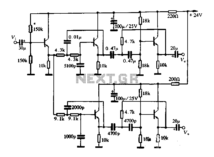
A band-pass filter is an essential electronic circuit that allows signals within a certain frequency range to pass while attenuating frequencies outside that range. The circuit typically consists of a combination of resistors, capacitors, and transistors configured to achieve the desired frequency response.
In a transistor-based band-pass filter, the transistors serve as active components that enhance the filter's performance by providing gain, which is crucial for maintaining signal integrity. The design typically incorporates both high-pass and low-pass filter sections, which are connected in such a way that the output only allows a specific band of frequencies to be transmitted.
The schematic usually includes two stages: the first stage is a high-pass filter formed by a capacitor in series with the input signal and a resistor connected to ground. This stage blocks low-frequency signals. The second stage is a low-pass filter, which consists of a resistor in series with the output and a capacitor connected to ground, effectively blocking high-frequency signals. The cutoff frequencies of these two stages determine the bandwidth of the filter.
Transistors in the circuit are often configured in a common emitter or common collector arrangement, depending on the required gain and impedance characteristics. The selection of transistor types, along with the values of resistors and capacitors, is critical to achieving the desired filter characteristics, including center frequency, bandwidth, and roll-off rate.
Careful consideration of the layout and component placement is also important to minimize parasitic capacitance and inductance, which can adversely affect filter performance. Proper biasing of the transistors ensures optimal operation and stability across the desired frequency range.
Overall, a well-designed band-pass filter using transistors can effectively isolate specific frequency components in a signal, making it a valuable tool in various applications, including audio processing, communications, and signal conditioning.Described in this article is a band-pass filter is a circuit diagram of transistors, as shown below.
Related Circuits
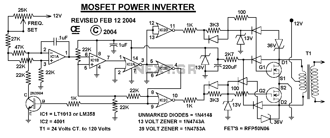
This power inverter circuit provides a stable square wave output voltage. The frequency of operation is set by a potentiometer and is typically adjusted to 60 Hz. Various off-the-shelf transformers can be utilized, or custom-wound transformers can be created...
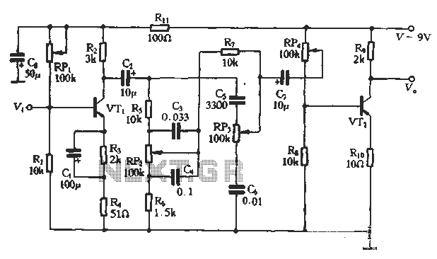
This article presents a diagram of an attenuated tone control circuit. The circuit primarily consists of transistors and RC networks as its components. The circuit operates in such a way that the shunt effect of capacitor C4 and resistor...
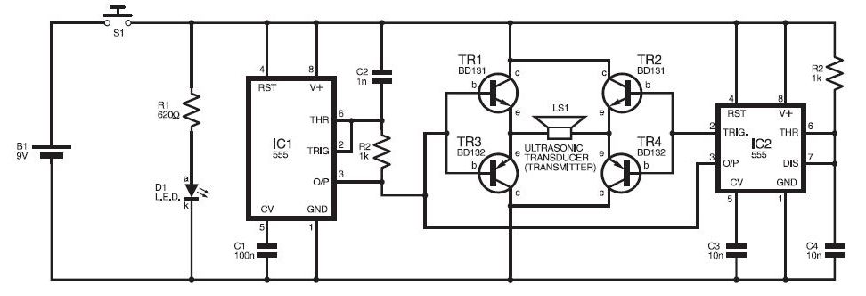
This ultrasonic sensor circuit consists of a set of ultrasonic receivers and transmitters that operate at the same frequency. When an object moves within the covered area, the circuit's balance is disturbed, triggering the alarm. The ultrasonic circuit is...
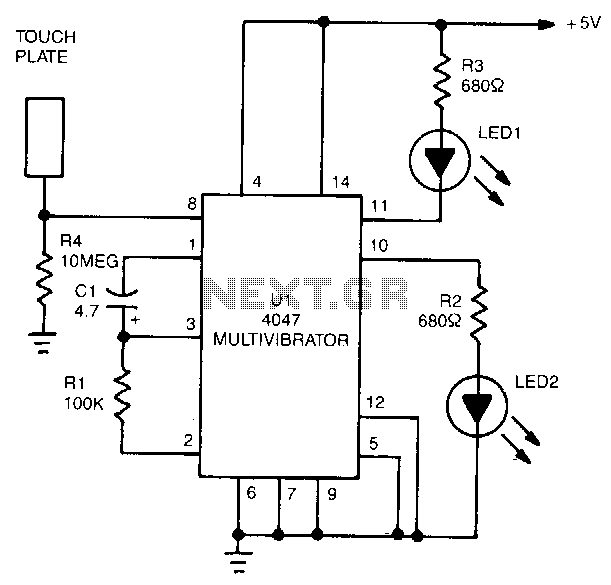
The 4047 is configured as a monostable multivibrator circuit, also known as a one-shot, which is triggered by a negative transition of the signal applied to its pin 6 input. The duration of the multivibrator's output pulse is determined...
The following circuit illustrates a Mains Remote-Alert Circuit Diagram. Features include simple circuitry, with the transmitted signal being conveyed effectively. The Mains Remote-Alert Circuit is designed to provide a notification system that alerts users about the status of mains power....
Modify it to click and latch a relay when the button is pressed from anywhere in the house. Additionally, if possible, unlatch the relay when pressed again. A flip-flop circuit may be created to take the first signal and...