
A control circuit diagram 555 pairs steady mode
The 555 timer IC is a versatile component commonly used in various electronic circuits. In bistable mode, the 555 timer operates as a flip-flop, allowing it to maintain its output state until it receives a triggering pulse. This mode is particularly useful in applications where two stable states are required, such as in memory storage, toggle switches, or motor control circuits.
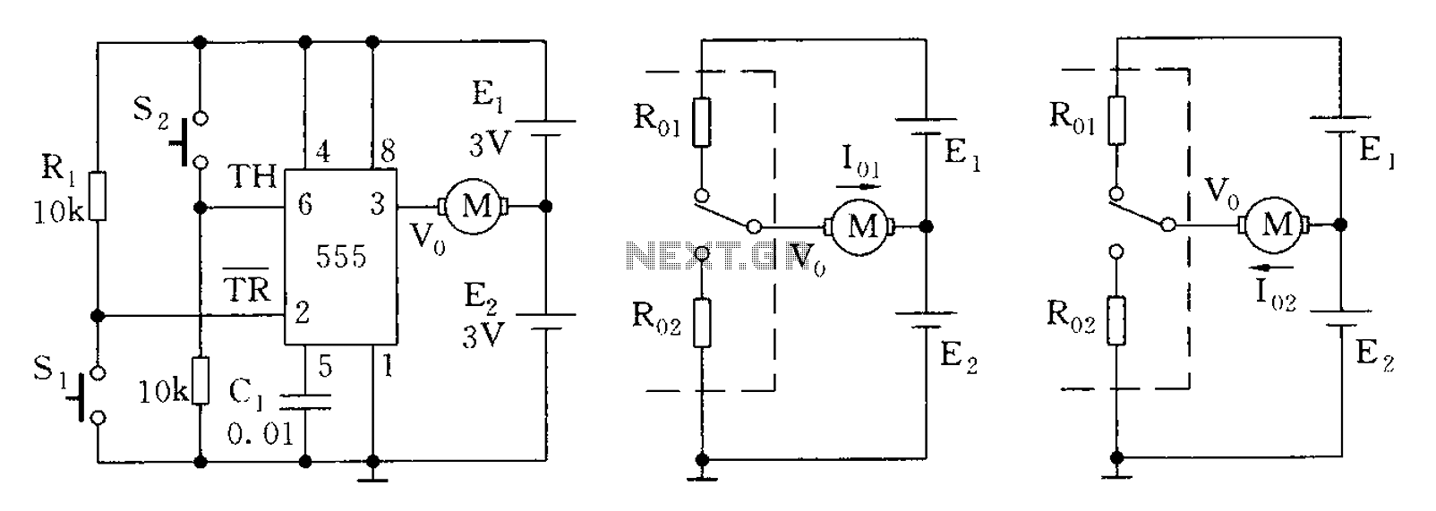
In the context of a micro-motor reversing control circuit, the bistable configuration allows for the control of the motor's direction. The circuit typically consists of a 555 timer, resistors, capacitors, and the micro-motor itself. When a trigger pulse is applied to the reset or set pin of the 555 timer, it changes the output state, thus reversing the direction of the motor.
The circuit diagram for this application would illustrate the connections between the 555 timer and the motor, as well as the necessary components to ensure proper operation. Resistors are used to set the timing characteristics, while capacitors may be included to filter noise or stabilize the power supply. The output of the timer directly controls the motor driver circuit, which may include transistors or relays to handle the motor's power requirements.
Overall, the bistable mode of the 555 timer offers a reliable solution for controlling devices such as micro-motors, providing a simple yet effective means of toggling between two states based on external inputs.555 bistable mode, stable and non-stable than single modes of application is relatively less. Bistable mode means that the circuit composed by R-S trigger mode. As shown by a m icro-motor reversing bistable mode control circuit diagram. 7b9bd92f536999.jpg onload if (this.width 620) this.wih 620; onclick window.open (this.src) style cursor: pointer alt Click to enlarge /
Related Circuits
It is essential to draw a circuit using a layout and conventions that are universally recognized. In electronic circuit design, adherence to standardized symbols and layout conventions is crucial for effective communication among engineers and technicians. A well-drawn schematic diagram...
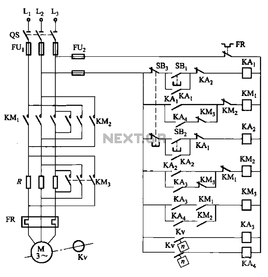
The circuit illustrated in Figure 3-130 differs from the circuit in Figure 3-129 in that when the stop button SB3 is pressed, the electric motor initiates braking. Furthermore, during both the startup and braking phases, the motor power lines...
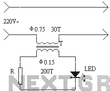
The installation of an electrical outlet in the refrigerator work light serves to enhance visibility of the refrigerator's interior while also improving the aesthetic appeal of the socket. The circuit is illustrated. Additionally, the circuit utilizes the secondary induced...
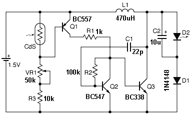
This is a short-range light barrier designed for use as an intruder alarm in doorposts and similar applications. The 555 timer in the transmitter oscillates at approximately 4.5 kHz. The short-range light barrier operates by utilizing a transmitter and a...
Adding a discharge path to the upper MOSFET of a cascode circuit significantly reduces the unavoidable Miller effect, thereby enhancing the Power Factor Correction (PFC) performance of a power supply's front end. In a cascode configuration, the upper MOSFET is...
This is a solar tracking circuit designed to harness power from sunlight. The circuit operates optimally by maximizing sunlight exposure to generate electricity. The solar tracking circuit utilizes a combination of photovoltaic (PV) cells, sensors, and a microcontroller to adjust...