
A high-power DC motor overcurrent protection circuit
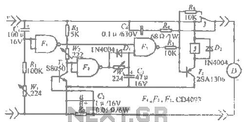
The described circuit is an advanced sampling and protection system designed for motor control applications. It integrates a sampling circuit that minimizes the resistance in the sampling path, which is essential for maintaining signal integrity and minimizing power loss. The inclusion of a DC voltage level between components allows for better signal processing and stability across varying operating conditions.
The line amplifier plays a crucial role in this circuit by amplifying the sampled signals for better analysis and control. It is equipped with adjustable magnification settings, allowing for fine-tuning based on specific operational requirements. This feature is particularly beneficial in applications where current levels may fluctuate significantly throughout the day, necessitating a robust protective mechanism.
The boot delay protection circuit is strategically designed to prevent premature activation during motor startup. By using a combination of capacitors and resistors, the circuit ensures that the output remains low until the capacitor reaches a specific voltage level. This delay is critical in preventing false triggering of the protection mechanism, which could lead to unnecessary power interruptions.
Moreover, the current detection circuit is essential for monitoring the motor's operational status. It utilizes various resistive and capacitive components to accurately measure the current and voltage levels. If the motor current surpasses the defined threshold, the protection circuit activates, generating a high output signal that initiates a delay sequence. This sequence allows the system to stabilize before taking further action, ensuring that any transient conditions do not result in immediate shutdown.
The use of flip-flop mechanisms enhances the reliability of the protection system by providing a self-locking feature that secures the circuit during fault conditions. This ensures that the motor remains protected even in the event of a sustained overload.
Finally, the configuration of components PV3 and C3 is vital for managing the return of current to its rated value. The rapid discharge capability of these components ensures that the system can quickly adapt to changing conditions, maintaining the sensitivity required for effective motor protection. Overall, this circuit design exemplifies a comprehensive approach to motor control, combining sampling accuracy with robust protection features.R "h sampling circuit limit order _" to reduce the sampling resistor. Plus DC voltage level can be placed between the nine-party agency. With the elbow through the magnification adjusting the line amplifier can / fH should whole day protection current. r cattle production is exposed under the action of the motor startup by c ,, R., wl, Fi and Fz composed boot delay protection circuit, just start, capacitor c.
no voltage, F output low .J '] is high, Paul charged by the terminal voltage of the capacitor cl gradually increased protection does not act.. (when there is a sufficient delay time when the rise of the sword must ask) f flip auxiliary} f {island village level, Magog lose thirty by w ,, Rz f .R other components of the current detection circuit control paste, the motor current hill .R, the pressure drop more, the lower level f collector voltage, motor current exceeds curse over protection the protection current, Mary output high, the roar, c, delay, after the exclusion of interference, n output low .J and self-locking action, cut off the electrical power supply circuit to protect the motor.
If pV3, C3 constitute the delay in the time when the current drops back rating, just by giant electric c D] on the rapid discharge, sensitivity to ensure the protection.
Related Circuits
The primary application area for brushless direct current motors (BLDC) is in positioning systems. Brushless Direct Current (BLDC) motors are widely utilized in various positioning applications due to their high efficiency, reliability, and precise control capabilities. These motors operate without...
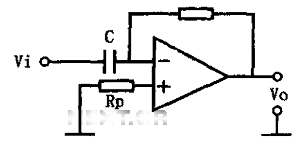
This circuit illustrates a basic differentiating circuit. The differential operation circuit can process input and output signals, establishing a relationship between the output and the input. A basic differentiating circuit is designed to produce an output that is proportional to...
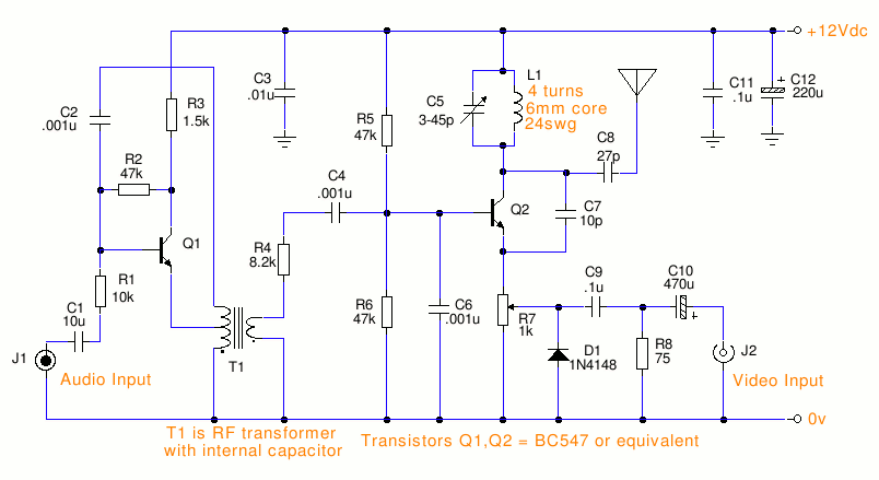
This is a small TV transmitter circuit that transmits in VHF, utilizing negative sound modulation and PAL video modulation. It is suitable for countries that use the B and G system. T1 refers to a type of transformer. The...
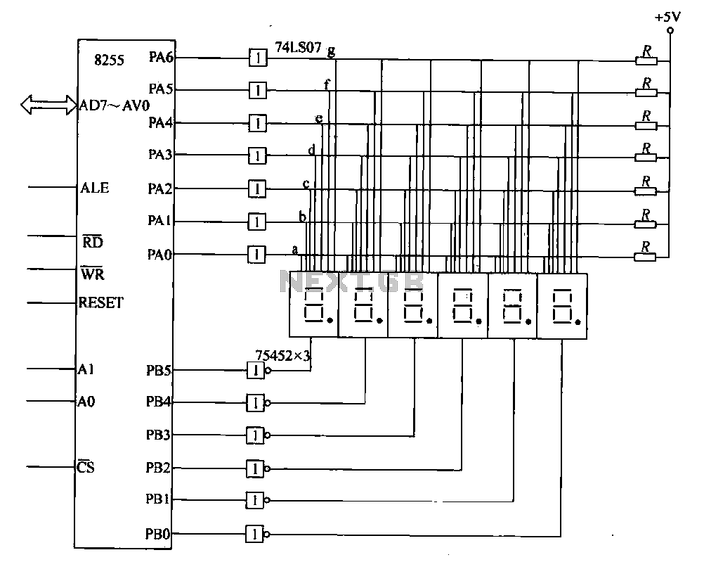
This circuit demonstrates a typical six-digit dynamic display configuration. It utilizes the PA 8255 for display output code and the PB port for bit selection code. The display buffer is designated as DISBUF, which processes the hexadecimal number obtained...

The intelligent control circuit for the iron is presented. This circuit utilizes the integrated circuit PT8A351X to manage functions such as direction detection, relay control, and LED indication. When the iron is positioned horizontally, it will power off after...
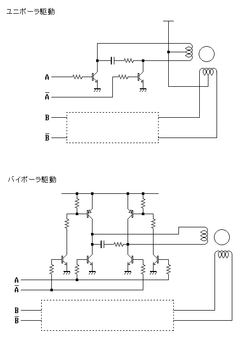
The first pulse motor that is used to position control. Features were incorporated for positioning control. This does not mean intelligent and autonomous driving the motor in response to movement commands from the host. The key to controlling the...