
A linear dimming controller
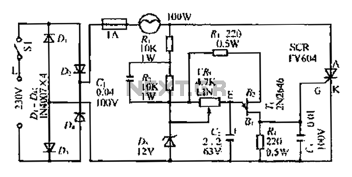
The circuit begins with an AC power source rated at 30V, which is fed into a rectification stage. The rectifier converts the AC voltage into a pulsating DC voltage. The positive output of the rectifier is connected to a fuse, which serves as a protective device to prevent overcurrent conditions that could damage the circuit components. Following the fuse, a 100W incandescent bulb is connected, which acts as a load and visual indicator of the circuit's operation.
The negative terminal of the rectifier is linked to a thyristor, a semiconductor device that controls the flow of current. The thyristor is used to switch the load on and off, allowing for control over the brightness of the bulb. The operation of the thyristor is influenced by the gate signal, which can be manipulated through the adjustment of a variable resistor (VR).
To ensure stable operation, a Zener diode is integrated into the circuit to provide a fixed bias voltage. This component helps to maintain consistent performance despite variations in input voltage or load conditions. The variable resistor allows for fine-tuning of the circuit, enabling the brightness of the bulb to be varied between approximately 15W and 60W. The adjustment of the VR changes the conduction angle of the thyristor, effectively modulating the power delivered to the load and, consequently, the brightness of the lamp.
This configuration not only provides a means of controlling the brightness of the lamp but also demonstrates fundamental principles of power electronics, including rectification, load control, and voltage regulation. The design is suitable for applications requiring adjustable lighting or other forms of load management.AC 30V through I). - After the dish rectified by its positive terminal connected to the fuse IA IOOW bulb, the negative terminal is directly connected to the thyristor connecte d overcast proud. DC voltage by IOOW bulb fork by horse, Makati to J2V Zener B. L radiation plate to provide a stable bias. Liao Xu rotation VRi, T-emitting rice Xu also like to increase the voltage. A wind so felt furrow end j Bu liters.., R Zhu silicon conduction angle increases, increasing the brightness of the lamp f drawer, figure VR value can IOOW lamp brightness in the range of about 15 to 60W under tJ One uniform change
Related Circuits
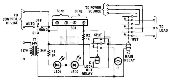
Relay K1 features a low-impedance coil, while Relay K2 is equipped with a high-impedance coil. When a sensor opens, current flows through the coil of K1, activating it. This action opens the contacts of K1, thereby preventing the reclosure...
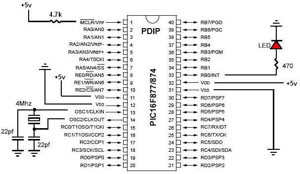
PIC development/testing board. This is a PCB design for a basic PIC16F877 development board. All that is required is a 4 MHz crystal, two 22 pF capacitors, and one 4.7 kΩ resistor. The PIC16F877 development board is designed to facilitate...
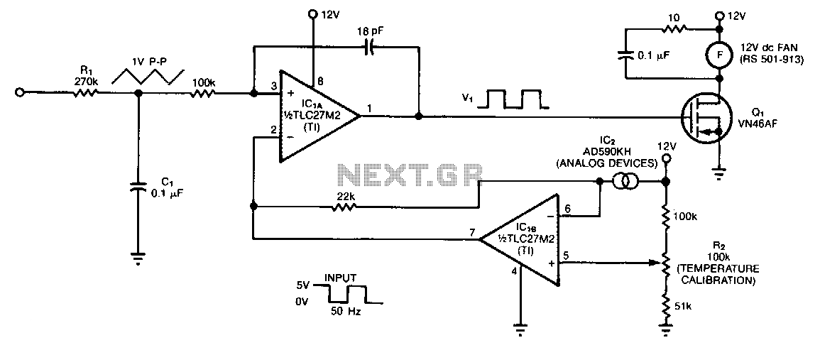
The controller circuit is designed to reduce a fan's noise, power consumption, and wear, especially when operating in low, fluctuating ambient temperatures. A temperature sensor is mounted in the fan's airstream, allowing the circuit to adjust the fan speed...
Wine doesn't like subzero temperatures, and during wintertime, my wine cellar got pretty cold. There was an electric heating element, but the thermostat was broken, so it was either full burn or nothing. That's how the temperature monitor/controller came...
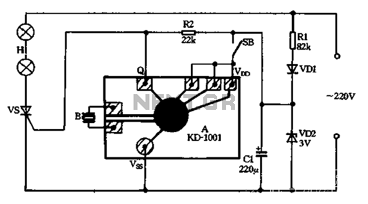
A 220V AC power supply is utilized through a resistor R1 to step down the voltage, followed by a rectifier VD1 and a filter capacitor C1, resulting in an output voltage of approximately 3V DC for the KD-1001 manifold....
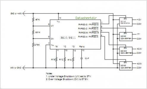
The PS10 saves board space, improves accuracy, eliminates optocouplers or level shifts, and reduces overall component count by combining four programmable timers, input under-voltage (UV) and over-voltage (OV) supervisors, a programmable power-on reset (POR), and four 90V open drain...
Warning: include(partials/cookie-banner.php): Failed to open stream: Permission denied in /var/www/html/nextgr/view-circuit.php on line 713
Warning: include(): Failed opening 'partials/cookie-banner.php' for inclusion (include_path='.:/usr/share/php') in /var/www/html/nextgr/view-circuit.php on line 713