
A Mixed-Signal LED Clock

The mixed-signal LED clock integrates both analog and digital functionalities, offering a unique approach to timekeeping. The design features an innovative combination of mechanical and electronic elements, allowing for a visually appealing and functional timepiece. The mechanical bell not only serves as an auditory indicator of the hour but also enhances the overall aesthetic of the clock, providing a nostalgic touch reminiscent of traditional clocks.
The matrix configuration of the LEDs allows for efficient multiplexing, where only one row of anodes is activated at any given time. This minimizes power consumption while maximizing the visual impact of the display. The choice of using discrete transistors for driving the LEDs ensures reliable operation and allows for easy adjustments to brightness through resistor selection. The use of a 12V supply voltage is particularly advantageous, as it enables the use of standard LED configurations while ensuring sufficient brightness for visibility.
The choice of the PIC16F84 microcontroller, despite its obsolescence, demonstrates a practical approach to utilizing available resources. The transition to the more modern PIC16F628 is straightforward, requiring minimal changes to the existing software, thus ensuring continued relevance of the design. The integration of the 74HC563 latch facilitates expanded output capabilities, allowing for more complex driving of the LED matrix without overwhelming the limited I/O of the microcontroller.
Overall, the mixed-signal LED clock presents a compelling example of how traditional clock design can be enhanced with modern electronic components, resulting in a unique and functional device that bridges the gap between analog and digital technologies.The term "mixed-signal" is usually reserved for circuits and ICs that process both analog and digital signals. In that sense the title "A mixed-signal LED clock" is perhaps misleading since this is a digital clock from beginning to end.
However, the readout is analog and since the beast had to be given a name, I a called it my "mixed-signal" clock . Somewhere in the middle of the eighties, when I was studying, I joined the ECA: the Eindhoven Computer Association, a microcomputer club in Eindhoven. Although I am not a member anymore, they still exist and have now been active for more than 25 years [1].
Being situated in Eindhoven, the club obviously had close links with Philips, and regularly obtained surplus supplies of components of various kinds. I remember that these components could be bought for fl 0. 10 (10 guider cents) a piece on every Tuesday evening. At one time they had a batch of LEDs in various shapes and colors. In those days a LED was not quite the common component it is today. The availability of these LEDs in these beautiful colors and nice shapes suggested the idea for a clock with an analog clock face.
Normally, I never bother about making a printed circuit board for my circuits. I prefer working on these cheap prefabricated pertinax breadboard cards. However, for the circular face of my LED clock I had no other alternative than to etch a PCB (Fig. 1). I made it in the summer of 1987, and after I had placed the LEDs and finished the wiring, I put it into a drawer. There it was forgotten due to more pressing projects (girls and examinations). Two years ago I found it again and decided to finish the clock. It actually became my first PIC processor project. The circuit of the clock contains no real surprises. A (literally) striking feature about this clock is that it has a real mechanical bell which strikes the hours.
It gives the clock quite an homely appearance, and it has became a much valued member of our household. As mentioned, the circuit of the "Mixed-Signal" clock is rather straight forward. Since the second, minute and hour LEDs could be time multiplexed, the LEDs are connected in a matrix (Fig.
2). The anodes of the LEDs are connected to the rows, the cathodes to the columns. For the hours hand, five LEDs connected in series have been used. This additionally sets the supply voltage to a minimum of 12V. Both for the anodes as well as for the cathodes, drivers with discrete transistors have been used. The two resistors of 330 ohm in the anode drivers set the current through the LEDs and hence their brightness. The left 330 ohm resistor (connected to rows A. E) sets the current through the seconds and minutes LEDs while the right LED (connected to row F) sets the current through the hours LEDs.
You will have to determine the proper value of these resistors experimentally. The value of 330 ohm is just a starting value and depends on the exact supply voltage, and the color of the LEDs used. Especially the resistor for the hours LEDs will be much smaller, typically something in the range of tens of ohms.
The 16F84 processor used here is a little bit out dated and no longer in production. I used it because of the simple fact that I had it lying around. The more modern 16F628 is pin compatible and will perform equally well. The 16F628 controller requires some minor software modifications. The source and hex files for both the 16F84 and the 16F628 have been included in the download section at the bottom of this page. The 16F84 has too few I/Os to address all the anode and cathode drivers directly (Fig. 3). A 74HC563 8 bits latch was used to extend the number of outputs by another 8 bits at the expense of a latch enable signal taken from port A.
The eight outputs from the latch, together with the lowest 4 bits of port B from the PIC drive address the cathode drivers. Since only one of the anode rows is switched on at any given moment, a HEF4028 1-o 🔗 External reference
Related Circuits
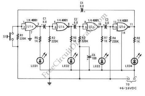
This schematic diagram illustrates a ring-around LED flasher circuit. The circuit operates by turning off two LEDs while activating the other two, continuing this pattern until the timing cycle reverses. The ring-around LED flasher circuit is designed to create a visually...
This circuit operates at 73 MHz and is designed for controlling halogen lights through radio frequency remote control. The primary function is to toggle the power state of a halogen lamp. When the button on the remote control is...
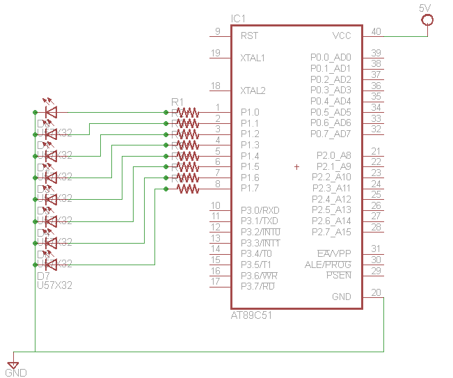
Learn how to interface LEDs with the 8051 Microcontroller. Download free source code and circuit diagram of the P89V51RD2 Microcontroller. Interfacing LEDs with the 8051 microcontroller is a fundamental project that serves as an excellent introduction to microcontroller applications. The...
This is the second part of the square root algorithm. It was developed during the final stages of finishing this website and reviewing this document for publication. While Part I focused on an empirical discovery for a sequential algorithm...
This circuit when used with a 555 timer will cause light emitting diodes to turn on and off more slowly. This will make the LEDs appear similar to incandescent lamps. The described circuit utilizes a 555 timer IC configured in...
This simple flash is very compact to build in such a brooch. I have the circuit extracted from a CD cover. The flash uses a 1.5 V supply, this is a penlight or a button cell to use. Capacitor...
Warning: include(partials/cookie-banner.php): Failed to open stream: Permission denied in /var/www/html/nextgr/view-circuit.php on line 713
Warning: include(): Failed opening 'partials/cookie-banner.php' for inclusion (include_path='.:/usr/share/php') in /var/www/html/nextgr/view-circuit.php on line 713