
A Stylophone
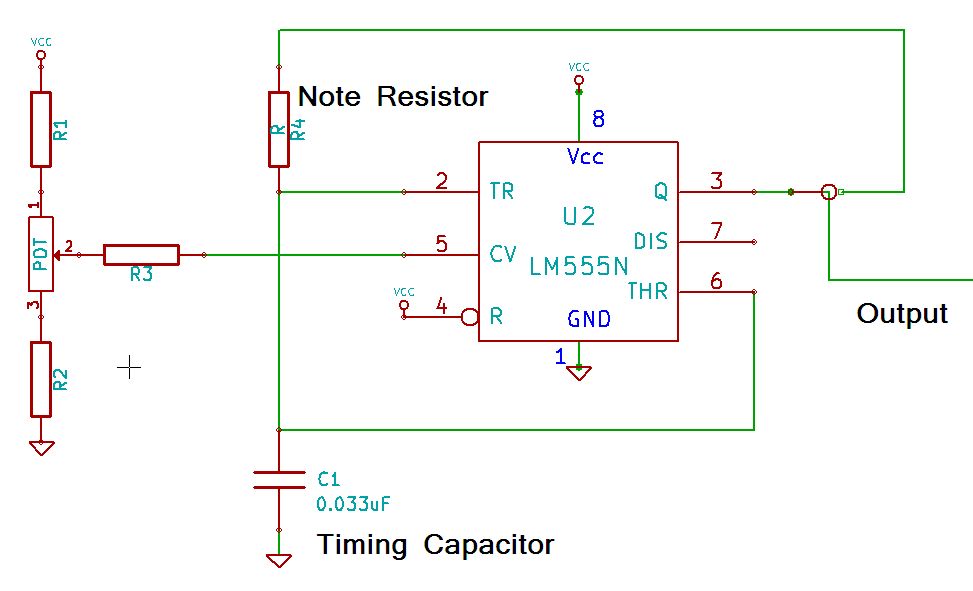
The schematic presented is an original design, free from intellectual property restrictions. It utilizes a 555 timer, which can be viewed as an extension of the recent "Know Your 555 Timer" article, alongside an LM386 audio amplifier to ensure sufficient volume. The printed circuit board (PCB) is designed for self-etching, and all components are readily available, allowing the Stylophone to be constructed for approximately $30 AUD. The PCB includes a breadboard area, enabling the addition of custom features such as a tremolo effect or an AtMega168 chip for enhanced digital-analog integration. The project has been successfully built and operated, although issues have arisen in subsequent attempts to use the base monostable circuit to generate a consistent tone. The circuit only produces a single click when connected, and the 555 timer overheats. Repeated checks of wiring and capacitor orientation have not resolved the issue. There are inquiries about replacing the resistive divider with an unassembled slide potentiometer, as well as questions regarding the grounding connections and the role of various connectors on the PCB. Additionally, there is interest in using resistive material for continuous frequency variation instead of stepped changes. Troubleshooting has revealed intermittent operation of the circuit, with brief functionality followed by failure.
The schematic incorporates a 555 timer configured in monostable mode, which is a popular choice for generating precise timing pulses. The LM386 audio amplifier is employed to amplify the output signal, ensuring that the sound produced is audible and clear. The design emphasizes ease of assembly and accessibility of components, making it suitable for hobbyists and educators alike.
The PCB layout is user-friendly, featuring designated areas for both the main components and a breadboard section for custom modifications. This flexibility allows users to experiment with additional features, such as tremolo effects, which can be achieved by integrating additional components like capacitors and resistors into the breadboard area. The inclusion of an AtMega168 chip provides opportunities for more advanced digital sound synthesis, enabling users to explore the boundaries of analog and digital sound generation.
For those encountering issues with the circuit, it is critical to verify all connections and component orientations meticulously. The overheating of the 555 timer suggests a potential short circuit or incorrect component placement. It may be beneficial to utilize a multimeter to check for continuity and ensure that no unintended connections exist.
Regarding the questions about the resistive divider and grounding, it is essential to confirm that all components intended for grounding are appropriately connected to the ground plane on the PCB. The connection of the stylus to pin 3 of the timer may serve a specific purpose in the design, potentially related to triggering or modulation functions, and should be examined in the context of the overall circuit operation.
For continuous frequency variation, using a piece of resistive material as a variable resistor could be a feasible solution. This approach would allow for a smooth transition between frequencies rather than discrete steps. Alternatively, a fixed resistor combined with a variable capacitor could achieve similar results, allowing for fine-tuning of the oscillator's frequency.
In summary, the project presents a versatile platform for sound synthesis, encouraging experimentation and customization while addressing common circuit design challenges. Proper troubleshooting and component management are crucial for successful implementation and operation of the circuit.The schematic that this is based on is my own, so it is free from Intellectual property restrictions. It is based around a 555 timer (so it could be an extension of the recent "Know Your 555 timer" article), and uses an ubiquitous LM386 audio amp so it can have enough volume to stand out from the crowd.
As with all of my projects, the PCB is designed for etching yourself, and there are no components that are difficult to source - in all, the Stylophone can be constructed for less than about $30AUD. There is a breadboard area on the PCB, so you can add your own tremolo, or even an AtMega168 chip if you feel inclined.
Allowing you to create the ultimate in digital analog fusion! (Sorry - I couldn`t resist) :-) I built this whole project once, and it worked perfectly. However, a year later, I`m trying to use the base monostable circuit to produce a set tone. For some reason, it only clicks once when hooked up, and the chip got hot enough to burn me. I`ve checked all wiring and capacitor orientation many times. Any ideas what`s going on This is a terrific project! great use of the 555, I have a question: is it posible to replace the resistive divider with an unassembled slide potentiometer like the one used in the tic tac tunes project ( If so, what should be its value the total resistance of the tune bank I am making this project, doing the PCB design in KiCad at the moment. So, there is a problem that can`t be solved: I simply can`t fill the piano keys. When choosing zone properties, they all should be connected to the ground, right If it`s so, connector P5 (which in the `real` circuit is the pen) is used for `grounding` the circuit Besides, I am curious about two other thing: why is the connector Stylus connected to timer`s pin 3 if in the `real` circuit is left unused Should Stylus and P5 be connected on the back side of the PCB I would be happy to etch and solder prep a board for you (or anybody who wants one).
I can make the board for $20+shipping - Just let me know where you are. I really like this, I took apart one of the "reissue" stylophones and the 555 still exists in the design, but another glop top chip is used to add envelope and vibrato to the sound. Anyway, I have a question - I want to make one of these but instead use a piece of resistive material with the stylus as the "wiper", like in a variable resistor, so the frequency is continuous rather than stepped, can you recommend anything to use Alternatively, can I use a fixed resistor and use some sort of variable capacitor Thinking about theremins.
I`m building one for myself (so thanks for schematics etc. ! :) ) but all I have for speakers/buzzers are rated as 8ohms 0. 5W little speakers. And I have two of them. No, the restsiance change is not consistient, as the oscilator is a loagrithmic device. As the frequency increases, the change in resistance needed to get to the next note decreases. Got the circuit working on a breadboard and wanted to make it permanent. Just finished up and I`m having some troubles. I checked the entire circuits connections trying to find a mistake. I can hear the circuit when I flip the switch because I hear a little noise, but after a second the circuit dies almost like a capacitor was discharging. When I get lucky I can play a note or two and it sounds great but then dies. Maybe I burned something up when I was soldering Any suggestions of help H 🔗 External reference
Related Circuits
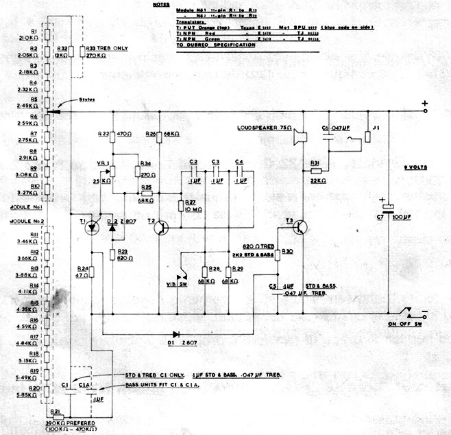
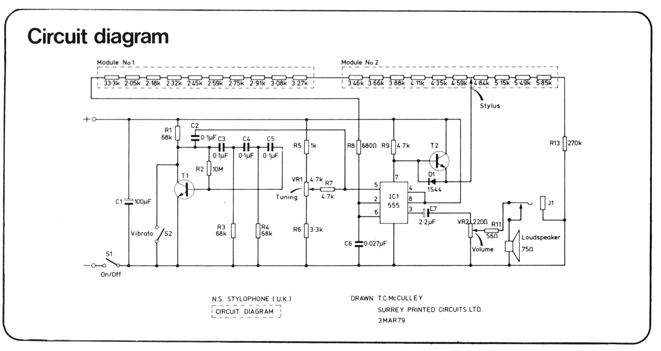
A recently discovered schematic appears to be authentic and does not include the 555 timer. Additionally, a picture of Brian Davis on this page shows him holding the etch mask, which does not exhibit any features resembling a socket...
The topic of alternative keyboard layouts has gained traction due to advancements in Software and MIDI technology, making it practical to explore different configurations. This post aims to clarify what alternative keyboard layouts are, distinct from other methods of...