
aam commander rc system
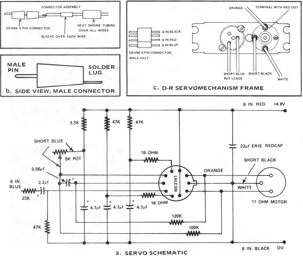
The AAM Commander RC System is a sophisticated radio control system designed for model aircraft, providing enhanced control and performance for hobbyists and enthusiasts. This system typically includes a transmitter, receiver, servos, and various electronic components that facilitate communication between the pilot and the model aircraft.
The transmitter serves as the control interface for the pilot, allowing for the manipulation of various control surfaces such as ailerons, elevators, and rudders. It operates on specific radio frequencies, ensuring reliable signal transmission to the receiver installed in the aircraft. The receiver, in turn, interprets the signals from the transmitter and translates them into mechanical movements through servos, which are responsible for adjusting the control surfaces accordingly.
In addition to the basic components, the AAM Commander RC System may incorporate features such as dual rates, which allow pilots to switch between different sensitivity settings for control inputs, and mixing capabilities that enable complex maneuvers by combining inputs from multiple channels. The system is designed to be user-friendly, ensuring that both novice and experienced pilots can operate their model aircraft with precision and ease.
The electronic schematic of the AAM Commander RC System would typically include the following key elements:
1. **Transmitter Circuit**: This section includes the oscillator circuit, modulation circuits, and power supply components that generate and transmit radio signals. The transmitter may utilize a microcontroller for signal processing and control logic.
2. **Receiver Circuit**: The receiver circuit includes an antenna, RF amplifier, demodulator, and servo output stage. The antenna captures the incoming radio signals, which are amplified and demodulated to extract the control information.
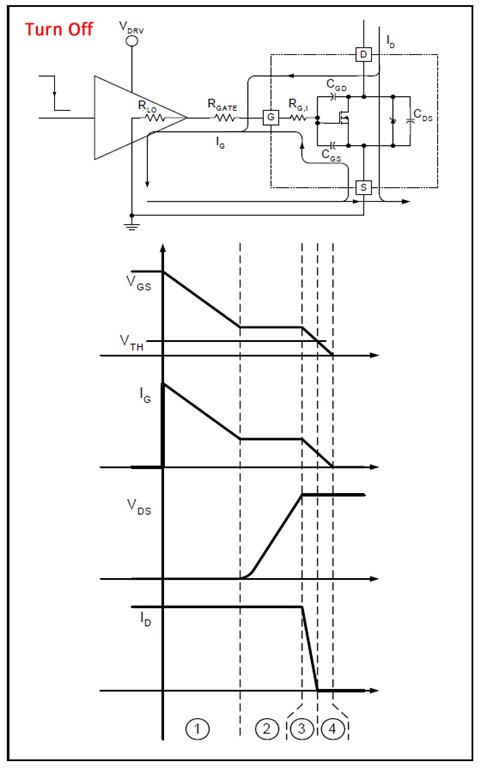
3. **Servo Control**: The servos are controlled by PWM (Pulse Width Modulation) signals generated by the receiver. The schematic would show the connection of the receiver output pins to the servo inputs, detailing the power supply and ground connections.
4. **Power Supply**: The power supply circuit is crucial for both the transmitter and receiver, ensuring that all components operate within their specified voltage and current ratings. It may include voltage regulators and filtering capacitors to stabilize the power supply.
5. **Antenna Design**: The schematic may also depict the design of the antenna used for both the transmitter and receiver, which is essential for achieving optimal range and minimizing interference.
Overall, the AAM Commander RC System represents a well-engineered solution for model aircraft control, showcasing the integration of various electronic components to enhance the flying experience.Part II of the AAM Commander RC System Article, scanned from the May 1972 edition of American Aircraft Modeler.. 🔗 External reference
Related Circuits
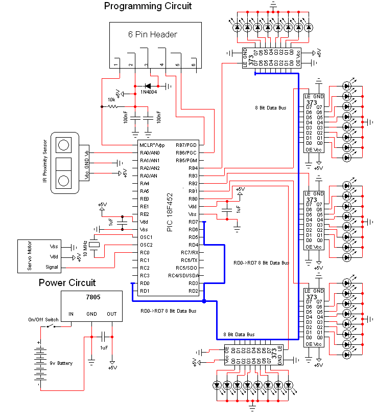
This document discusses a do-it-yourself alarm system utilizing the PIC18F452 microcontroller. It is a highly engaging project, although the schematic is quite complex. The project employs three main components to create the personal alarm system. The infrared (IR) proximity...

The solar orientation circuit employs a comparator with window control to maintain engine idle as long as the two LDRs (light-dependent resistors) are exposed to equal illumination. In this scenario, half the supply voltage is applied to the non-inverting...
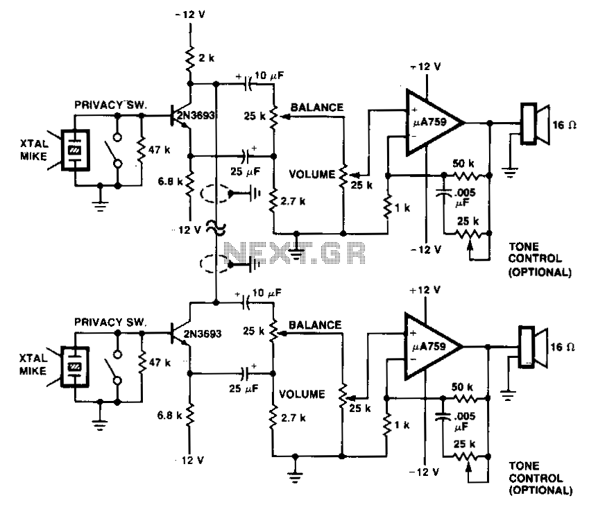
This system utilizes p.A759 audio IC devices and a shared connection between the preamplifiers as an interconnect. Either microphone can drive either speaker. Duplex operation is achievable with a single cable consisting of two wires. The system design incorporates the...
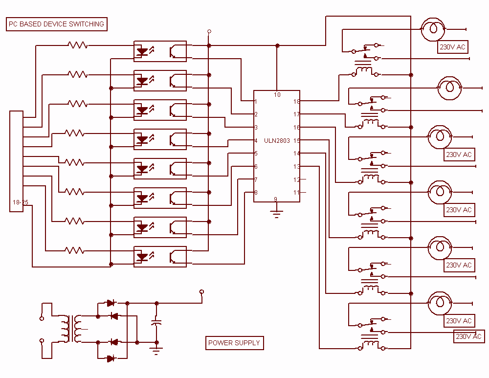
This project describes a new economical solution of home light control systems. The presented home light control system can be used for different sophisticated home applications. The control system consists of a PC, and control circuitry and the electrical...
H-bridge applications for robots, robotics, and motor control. This post focuses on the low-side switch element. H-bridges are widely utilized in robotics and motor control applications to enable bidirectional control of DC motors. An H-bridge consists of four switches arranged...
The SA9618A is designed for ALPC and signal conversion between a CD optical pickup and a decoding chip. This integrated circuit (IC) features an interconnection for a general CD optical pickup photodiode bias voltage VREF generation circuit, an RF...