
ac I need help matching parts
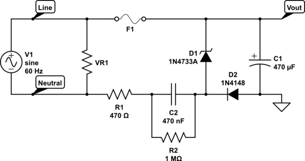
The circuit design involves integrating a PIC microcontroller with a transformerless power supply circuit, which is often chosen for its compactness and efficiency in low-power applications. The transformerless design must adhere to safety considerations, particularly concerning isolation from the mains voltage. The phase control circuit will be responsible for regulating the power supplied to the AC motors, allowing for speed control of the blower motor while ensuring that the lift motor receives full power.
In this configuration, TRIACs will serve as the primary switching devices. When selecting TRIACs, it is essential to ensure that they can handle the operational requirements, including the maximum current rating and gate characteristics. The L6004L3-ND TRIAC is a suitable candidate, but careful examination of the datasheet is necessary to confirm the gate current specifications and ensure compatibility with the PIC microcontroller's output.
The microcontroller's output pins will indeed provide a 5V signal, which exceeds the gate voltage requirement for the TRIACs. A voltage divider or a gate driver circuit may be employed to reduce the voltage to the appropriate level, ensuring reliable operation without exceeding the TRIAC's gate voltage rating. The gate current requirement of 3mA must be met to ensure proper triggering of the TRIAC. The datasheet indicates a maximum gate current; however, it is crucial to interpret this correctly to avoid damaging the component.
The need for opto-isolation arises from the requirement to protect the microcontroller and the low-voltage control circuitry from high-voltage spikes and transients that may occur in the AC circuit. An opto-isolator can provide the necessary isolation while allowing control signals to pass through. This is particularly important in applications where safety is paramount, such as in household appliances.
In summary, the design will require careful selection of components, including the TRIACs, opto-isolators, and appropriate protective measures. Understanding the specifications in the datasheets will facilitate the selection of compatible components and ensure the reliability and safety of the overall system.I want to use a picMicro 5v microcontroller combined with the figure 10 circuit from Link1 (Shown below) and a circuit similar to Link2 for motor control. It has to control 2 AC motors at 4 amps each (but the programming will make sure only one motor can turn on at a time).
I can`t afford SSR`s to handle that (according to digikey) so I`ll go with triacs instead. What parts do I need Long version: I`m building a new control board for a pop-up range hood. I plan on combining the figure 10 circuit from Link1 (transformerless power supply with safety considerations) with a phase control circuit similar to Link2. The actual parts from the phase control circuit won`t work, as my range hood states a usage of 4 amps.
I don`t see how the blower can use that much, so I suspect it is a rating if both the blower and the lift are running at the same time, but I can`t say for sure, so each of my triacs have to be rated for 4A and I`ll just make sure by programming that they aren`t driven at the same time (and it will be fuse protected as well). One of the triacs (for the lift) will only be driven full-phase, while the blower will be driven at 3 speeds.
I`ve done a lot of electrical work, so that`s not an issue, and the programming won`t be an issue, but I haven`t done much electronics work, so reading the numbers are actually giving me the most problems. I`m going to use one of the picMicro chips running at 5v. That means the output pins will be at 5v, right But the max gate voltage for any of the triacs on digikey are 2.
5v. Do I need a voltage dropper to get the output pin voltage to 2. 5v One of the triacs I`m considering is part L6004L3-ND at digikey. Digikey`s chart says it uses 3ma gate current, but am I reading the data sheet right that it could draw up to 1. 2A at the gate Also, that triac isn`t opto-isolated, but still appears to be isolated to 2500v If that`s the case, do I need an opto-isolator Basically, I need to know which parts will go together, but I`d also like to know how I`m supposed to read these datasheets and such so that I can figure it out for myself next time.
🔗 External reference
Related Circuits
A circuit design has been conceptualized, and an Assembly code program has been drafted for a three-level mini system. The described circuit design focuses on a three-level mini system, which can be interpreted as a hierarchical structure where each level...
A long-time observer has acquired four vintage amplifiers for their enclosures, but with limited knowledge of older equipment, they have not made much progress. The project involves the restoration and utilization of vintage amplifiers, which typically feature discrete component designs...
What type of microphone or mouthpiece can be used to connect to a POTS (Plain Old Telephone Service) telephone line to send DTMF (Dual-Tone Multi-Frequency) tones only, without transmitting voice? Is a standard microphone suitable, or must it be...
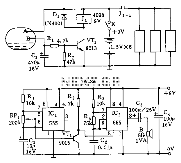
The call is triggered by the position sensing circuit, which activates the control circuit and SOS alarm circuit. This system is designed for critically ill patients or to assist disabled individuals in the event of a fall. A position...
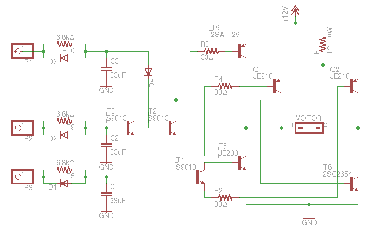
An old RC car is available, but it lacks the transmitter. A custom receiver/transmitter has been built using a microcontroller and a 2.4 GHz transceiver. However, there is uncertainty regarding the functionality of the car's original H-Bridge circuit. The H-Bridge...
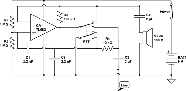
The circuit operates in receive mode, with the Push-To-Talk (PTT) switch enabling transmit mode. The speaker functions as both a microphone and a speaker. Most systems observed utilize a rocking armature transducer for the speaker. There is no base...
Warning: include(partials/cookie-banner.php): Failed to open stream: Permission denied in /var/www/html/nextgr/view-circuit.php on line 713
Warning: include(): Failed opening 'partials/cookie-banner.php' for inclusion (include_path='.:/usr/share/php') in /var/www/html/nextgr/view-circuit.php on line 713