
Ac-line-voltage-announcer
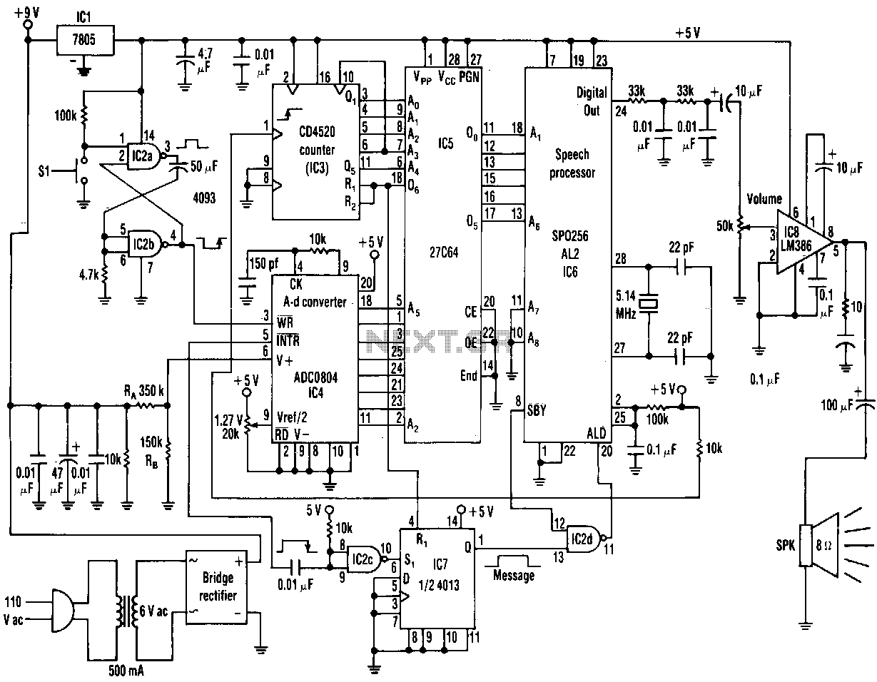
The range of this AC voltage monitor is 100 to 140 Vac, with a resolution of 1 V. The speech processor interprets an 8-bit binary input code from an analog-to-digital converter. The processor's pulse-code-modulated output then passes through a filter and an amplifier before driving the circuit's speaker to vocalize the corresponding number. Each time switch S1 is pressed, the speech processor program enunciates the monitored voltage readings from 100 to 140 V, depending on the code at the input of a 27C64 EPROM. The voltage-monitoring circuit consists of a bridge rectifier, filter capacitors, and a 10-kilohm load resistor. A divider, RA and RB, limits the input voltage to a maximum of 2.55 V. The analog-to-digital converter, IC4, then sends the voltage reading to the 27C64 EPROM, IC5. Pressing S1 sends a negative transient pulse to the write (WR) input of the analog-to-digital converter, IC4, which initiates a 100 µs conversion process.
The AC voltage monitor circuit is designed to accurately measure AC voltages in the range of 100 to 140 Vac. It employs a bridge rectifier to convert the AC input into a DC voltage, which is then smoothed by filter capacitors to eliminate ripple. The resulting DC voltage is fed into a voltage divider composed of resistors RA and RB, which scales the voltage down to a level suitable for the analog-to-digital converter (ADC), IC4. The maximum voltage that can be input to the ADC is limited to 2.55 V to ensure safe operation and accurate readings.
The ADC, IC4, processes the incoming voltage and converts it into an 8-bit binary code. This digital representation of the voltage is then sent to the 27C64 EPROM (IC5), where it is stored for further processing. The speech processor interprets this binary code and generates a pulse-code-modulated (PCM) output that is filtered and amplified before being sent to the speaker. The speaker vocalizes the corresponding voltage reading, providing audible feedback to the user.
The operation of the circuit is initiated by pressing switch S1, which generates a negative transient pulse that triggers the write input (WR) of the ADC, IC4. This pulse starts the conversion process, which lasts for approximately 100 microseconds. During this time, the ADC samples the voltage and updates the EPROM with the new reading. The entire system is designed to provide real-time monitoring and vocalization of the AC voltage, making it user-friendly and accessible for various applications.The range of this ac-voltage monitor is 100 to 140 Vac, with a resolution of 1 V. The speech processor interprets an 8-bit binary input code from an analog-to-digital converter. The processor"s pulse-code-mod ulated output then passes through a filter and an amplifier before driving tbe circuit"s speaker to vocalize the corresponding number. Each time switch S1 is _pressed, the speech-processor program enun ciates tbe monitored voltage readings from 100 to 140 V, depending on the code at the input of a 27C64 EPROM.
The voltage-monitoring circuit consists of a bridge rectifier, filter capacitors, and a 10-Kilload resis tor. A divider, RA and RB, limits the input voltage to a maximum 2.55 V. The aid converter, IC4, then sends the voltage reading to tbe 27C64 EPROM, ICS. Pressing Sl sends a negative transient pulse to the write, WR, input of the aid converter, IC4, which initiates a 100-ttS conversion process.
🔗 External reference