
AC Motor Speed Controller Kit
The AC Motor Speed Controller Kit - K2636 is designed to regulate the speed of AC motors, making it suitable for various applications such as fans, pumps, and other motor-driven devices. The circuit employs a phase control technique, allowing for smooth speed adjustments by altering the effective voltage applied to the motor.
The core components of the circuit typically include a triac, which serves as the primary switching device, and a diac for controlling the triggering of the triac. The control circuit often integrates a potentiometer that enables the user to adjust the motor speed according to specific requirements.
In operation, the circuit receives an AC input voltage, which is then processed through the triac. The phase control method involves delaying the triggering of the triac during each AC cycle, effectively reducing the power delivered to the motor. This delay can be finely adjusted using the potentiometer, allowing for a wide range of speed control.
Additional components may include resistors and capacitors that help filter noise and stabilize the circuit, ensuring reliable performance. The design may also incorporate safety features such as fuses or thermal protection to prevent overheating and damage to the motor or the controller itself.
Overall, the K2636 circuit diagram represents a practical solution for controlling AC motor speed, providing flexibility and efficiency for various applications.The? following circuit shows about AC Motor Speed Controller Kit - K2636 Circuit Diagram. Features: normal dimmers the kit performs, with carbon . 🔗 External reference
Related Circuits
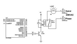
A relay can be controlled using a PIC microcontroller. The circuit illustrates how to control a single relay with the PIC 16F628. When the RB5 port of the PIC is set to high, the relay will activate. This circuit...
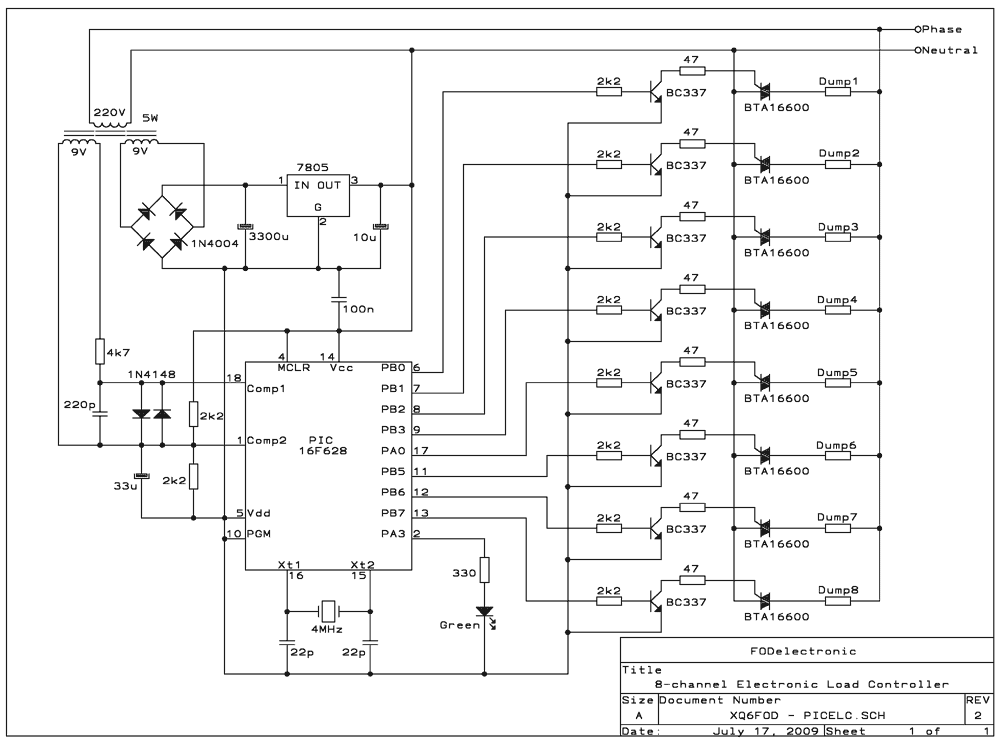
The ELC presented here has some flexibility, thanks to being software-controlled, but also has its limitations: It's intended for microhydro systems that employ a single-phase synchronous alternator, working at 220-240V, 50Hz, in a power range up to 25 kilowatts,...
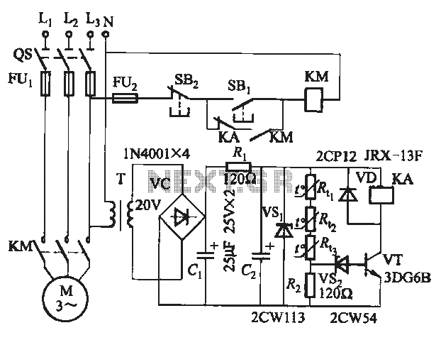
The semiconductor thermistor is an embedded thermal protection element that is sensitive to temperature, with a temperature error of 5 degrees. It offers reliability, a small size (diameter 3.5 mm), and ease of installation, making it suitable for embedding...
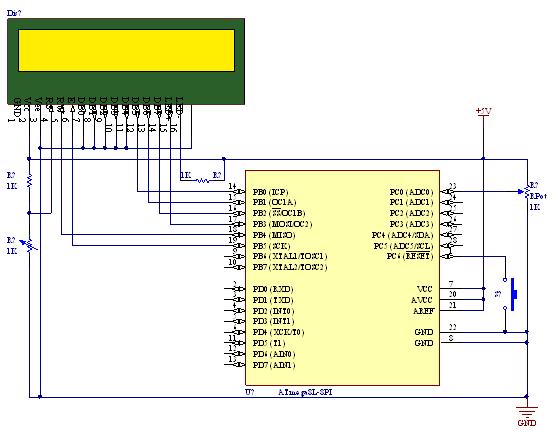
A straightforward tutorial on utilizing the ADC (Analog to Digital Converter) unit of the AVR microcontroller, demonstrated with the Atmega8, including a circuit diagram and code examples. The ADC unit in the Atmega8 microcontroller is a crucial component that allows...
The program utilizes two pulse width variables, pw1 and pw2, along with two sets of routines—left1 and left2, and right1 and right2—designated for each motor. The schematic illustrates that the first servo is connected according to the previous circuit...

This document outlines the installation process for a SPY5000 two-way motorcycle alarm on a 1998 Honda CB250 Nighthawk motorcycle. The SPY5000 two-way motorcycle alarm system is designed to enhance the security of motorcycles by providing features such as remote...
Warning: include(partials/cookie-banner.php): Failed to open stream: Permission denied in /var/www/html/nextgr/view-circuit.php on line 713
Warning: include(): Failed opening 'partials/cookie-banner.php' for inclusion (include_path='.:/usr/share/php') in /var/www/html/nextgr/view-circuit.php on line 713