
Accurate 50Hz Oscillator Circuit Using 555 And 7490
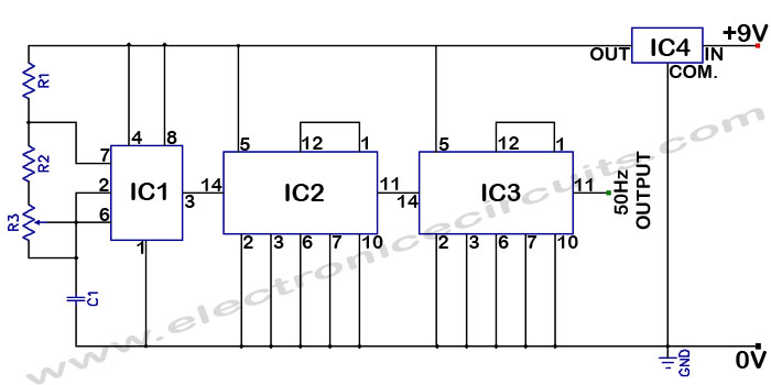
The circuit utilizes a 555 timer configured in astable mode to produce a square wave output. The frequency of oscillation is determined by the resistors and capacitors connected to the timer. Typically, standard values for resistors R1 and R2 and capacitor C1 are chosen to achieve the desired frequency of 50Hz.
The output from the 555 timer is fed into the first 7490 decade counter. This counter divides the frequency of the incoming pulse by ten. The output from the first 7490 is then connected to a second 7490 counter, which further divides the pulse by ten. The final output from the second 7490 will be a 50Hz signal, which is the desired frequency for this application.
The 555 timer's duty cycle can be adjusted by varying the resistor and capacitor values, allowing for flexibility in the pulse width. The 7490 counters are versatile and can be cascaded to achieve different division ratios, making this circuit adaptable for various frequency requirements.
Power supply considerations should also be noted; typically, a 5V to 15V DC supply is used for the 555 timer and 7490 counters. Proper decoupling capacitors are recommended near the power pins of the ICs to minimize noise and improve stability.
In summary, this circuit effectively generates a stable 50Hz pulse using a combination of a 555 timer and two 7490 decade counters, making it suitable for applications requiring precise timing signals.Accurate 50Hz Oscillator Circuit Using 555 And 7490 This circuit is a getting a 50Hz pulse. It comprises a 555 timer and two 7490 divide-by-ten.. 🔗 External reference
Related Circuits
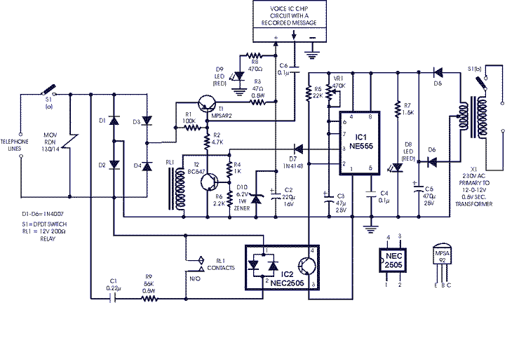
This circuit is not highly critical and can utilize various devices (such as a tape player with a message recorded on an endless tape) that do not overload the circuit or the telephone line. The incoming line is safeguarded...
Probes or contacts may utilize a non-reactive metal. Gold or silver plated contacts from an old relay may be used; however, a cost-effective alternative is to wire alternate copper strips from a piece of veroboard. These will eventually oxidize,...
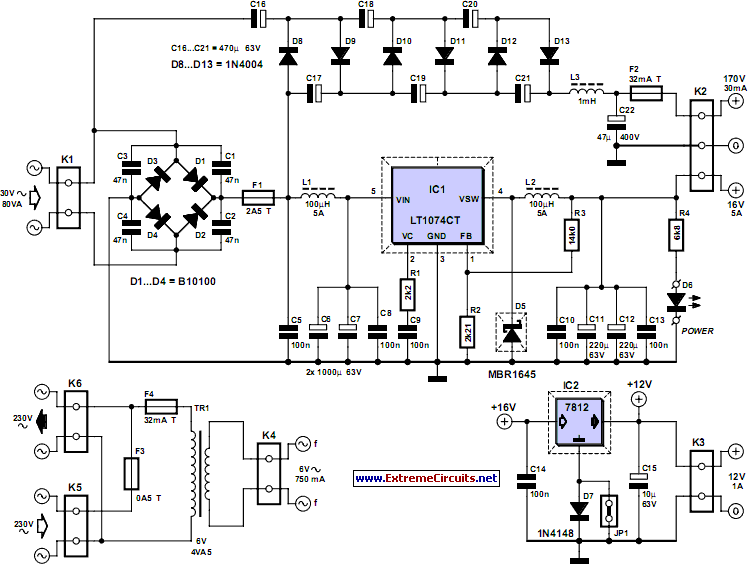
This power supply was designed for use with the Simple hybrid amplifier published elsewhere in this issue. It is suitable for various applications as well. A cascade generator is utilized for the 170 V output, a switch-mode supply provides...
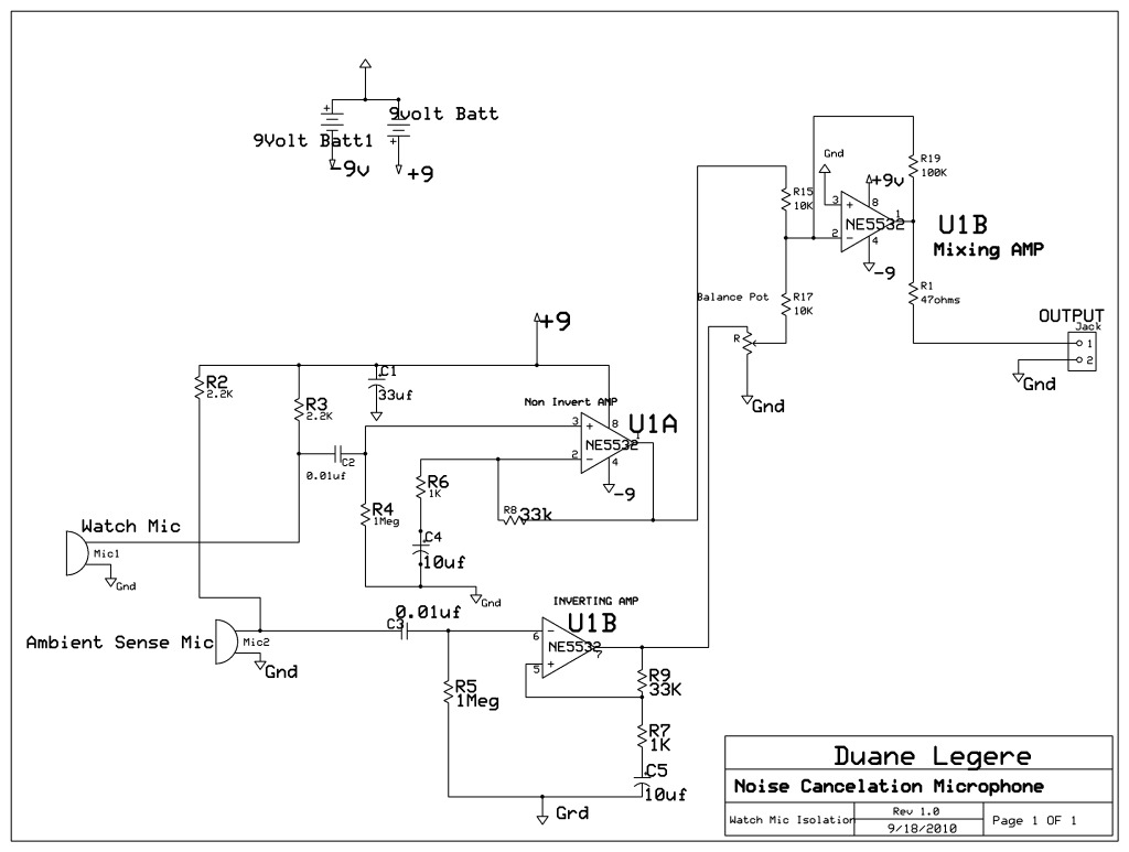
A microphone is designed to listen to a wristwatch while canceling ambient noise in the room. A circuit has been included, which is based on a headphone cancellation circuit. The schematic will be provided shortly. The suggested approach is...
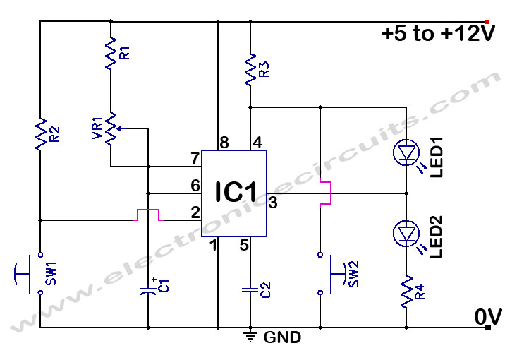
The 555 Timer Time Delay Circuit uses LEDs to visually indicate the status of the circuit at any moment. The operation begins when the reset switch, SW2, is activated. The 555 Timer is a versatile integrated circuit widely used for...

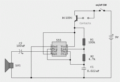
A simple circuit that can generate an inverted square wave similar to the one used by the inventor on his function generator. To construct a circuit that produces an inverted square wave, a basic approach involves using a 555 timer...
Warning: include(partials/cookie-banner.php): Failed to open stream: Permission denied in /var/www/html/nextgr/view-circuit.php on line 713
Warning: include(): Failed opening 'partials/cookie-banner.php' for inclusion (include_path='.:/usr/share/php') in /var/www/html/nextgr/view-circuit.php on line 713