
Active-limiting-amplifier
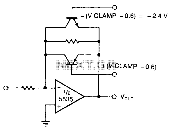
The modified inverting amplifier employs an active clamp to precisely limit the output swing. Consideration must be given to the VBE of the transistors. The output swing is restricted by the base-emitter breakdown of the transistors. A straightforward circuit configuration utilizes two back-to-back zener diodes across the feedback resistor; however, this method typically results in less accurate limiting and lacks ease of control.
The modified inverting amplifier circuit integrates an active clamp mechanism to maintain output voltage within a defined range, enhancing performance in applications where precise voltage levels are critical. The circuit's design must accommodate the base-emitter voltage drop (VBE) of the transistors, which plays a significant role in determining the operational limits of the amplifier. The active clamp functions by dynamically adjusting the feedback path, ensuring that the output does not exceed a specified threshold, thereby preventing distortion and saturation.
In contrast to simpler designs that utilize back-to-back zener diodes across the feedback resistor, the active clamp approach provides superior precision in voltage limiting. While the zener diode configuration is straightforward, it suffers from inherent limitations in control and accuracy due to the fixed breakdown voltage of the zeners, which can vary with temperature and manufacturing tolerances. The active clamp, on the other hand, can be designed to respond to varying input conditions, allowing for more consistent performance across a range of operating scenarios.
The circuit typically consists of operational amplifiers configured in an inverting configuration, with the active clamp implemented using additional transistors and feedback mechanisms. The transistors are selected based on their breakdown characteristics, ensuring that the clamp engages before the output voltage reaches critical levels that could lead to amplifier failure or signal distortion. Proper biasing and component selection are essential to optimize performance and reliability in the modified inverting amplifier design.The modified inverting amplifier uses an active clamp to limit the output swing with precision. Allowance must be made for the V8E of the transistors. The swing is limited by the base-emitter breakdown of the transistors. A simple circuit uses two back-to-back zener diodes across the feedback resistor, but tends to give less precise limiting and cannot be easily controlled. 🔗 External reference
Warning: include(partials/cookie-banner.php): Failed to open stream: Permission denied in /var/www/html/nextgr/view-circuit.php on line 713
Warning: include(): Failed opening 'partials/cookie-banner.php' for inclusion (include_path='.:/usr/share/php') in /var/www/html/nextgr/view-circuit.php on line 713