
Add a signal-strength display to an FM-receiver IC
The integrated circuit (IC) described operates using a frequency-locked loop (FLL) architecture, which is essential for achieving stable frequency modulation in radio frequency applications. The FM discriminator's filtered output modulates the local oscillator, enabling negative feedback that effectively compresses the output signal from the mixer. This compression is crucial for processing narrowband FM signals, allowing the intermediate frequency (IF) bandpass filter and the FM discriminator to efficiently handle the signal bandwidth.
The design indicates that with a compression factor of K=3, the original FM bandwidth of 180 kHz is reduced to 60 kHz, simplifying the design requirements. The implementation of a simple active filter using operational amplifiers (op-amps) negates the need for more complex components such as ceramic filters or LC tank circuits, making the circuit design more cost-effective and easier to manufacture.
The correlation muting system integrated into the IC is designed to mitigate interstation noise and unwanted spurious responses that can occur due to detuning. A second mixer within the muting circuit aids in this suppression, with its output available at Pin 1 for external applications, such as a detuning indicator.
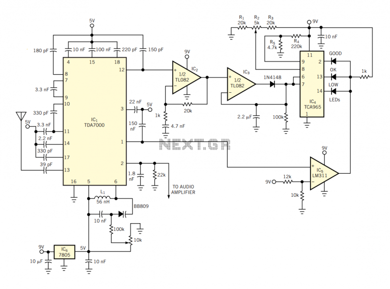
Signal strength detection is facilitated through the output of the IF filter at IC1, Pin 12. This voltage, centered around 70 kHz, can be processed using standard op-amps. The output is dc-coupled to an amplifier (IC2), followed by an envelope detector (IC3) that generates a dc voltage proportional to the strength of the received signal.
The TCA965 window discriminator (IC4) plays a pivotal role in comparing the envelope voltage against a reference voltage derived from resistors R1, R2, and R3, which define the center of the window, while R4 and R5 set the half-width. The results of this comparison are visually indicated by three LEDs, which represent different signal strength levels (Low, OK, Good). However, these indicators are only valid when the tuning is correctly aligned. When properly tuned, the voltage at IC1, Pin 1 reaches its maximum, prompting the LM311 comparator (IC5) to enable the TCA965, ensuring accurate signal strength representation. This comprehensive approach to signal processing and display enhances the overall functionality of the device in radio frequency applications.The IC has an FLL (frequency-locked-loop) structure. The filtered output of the FM discriminator frequency-modulates the local oscillator to provide negative-feedback modulation. The result is compression of the signal at the output of the mixer. Thus, the IF bandpass filter and the FM discriminator deal with narrowband FM signals. For a compression factor of K=3, the original FM bandwidth reduces to 180/3=60 kHz. So, you need neither ceramic filters nor complex LC tank circuits to realize the IF filter. A simple active filter using op amps can fulfill the task. The IC incorporates a correlation muting system that suppresses interstation noise and spurious responses arising from detuning.
The muting circuit uses a second mixer. Its output is available at Pin 1; you can use it to drive a detuning indicator. You can add a signal-strength display to the TDA7000 using the circuit in Figure 1.
You can obtain the information related to the intensity of the received signal at the output of the IF filter (IC1, Pin 12). You can easily process this voltage with common op amps, because the IF signal is centered on 70 kHz.
The voltage at Pin 12 is dc-coupled to an amplifier, IC2. Next, an envelope detector, IC3, yields a dc voltage proportional to the received-signal strength. The Siemens (www.siemens.com) TCA965 window discriminator, IC4, compares this envelope voltage with a voltage derived from R1, R2, and R3 for the window's center (and R4 and R5 for the window's half-width). Three LEDs show the result of the comparison (Low, OK, Good), but the display is valid only if the tuning is correct.
If it's correct, the voltage at IC1, Pin 1 reaches its maximum value, and the LM311 comparator, IC5, enables the TCA965.
Related Circuits
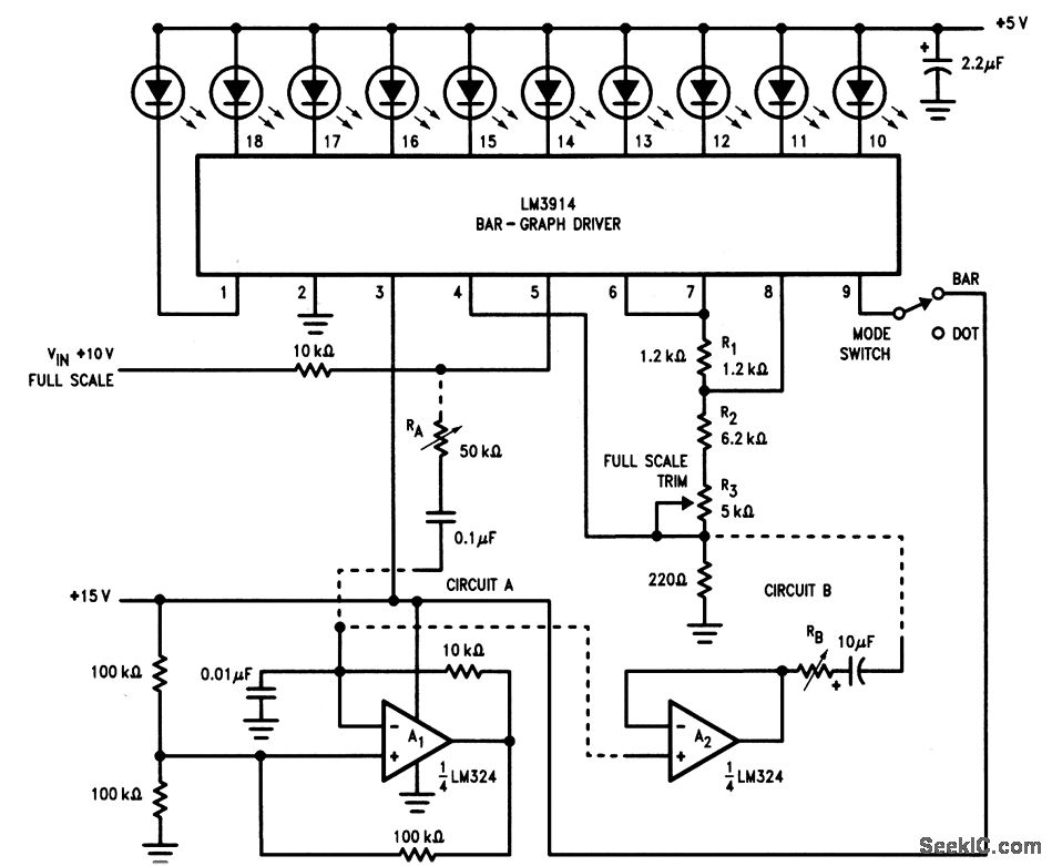
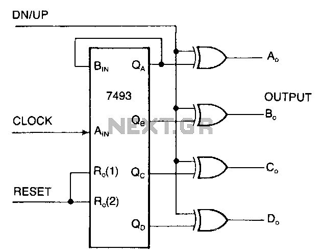
This circuit is an enhanced version of the display shown in Fig. 3-28, utilizing a triangular-wave oscillator. When the resistor RA is adjusted correctly, each incremental change in the input voltage (VIN) can be detected, allowing the glow from...
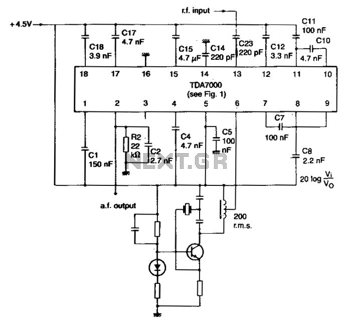
The local oscillator is controlled by a crystal, and the intermediate frequency (i-f) swing is minimally compressed. To prevent significant distortion of the demodulated audio signal, the deviation of the transmitted carrier frequency due to modulation must be limited....
This circuit is suitable for a small office or home environment. It can also be adapted to use a combination lock or keypad for setting and resetting. The described circuit functions as a security system tailored for small office or...
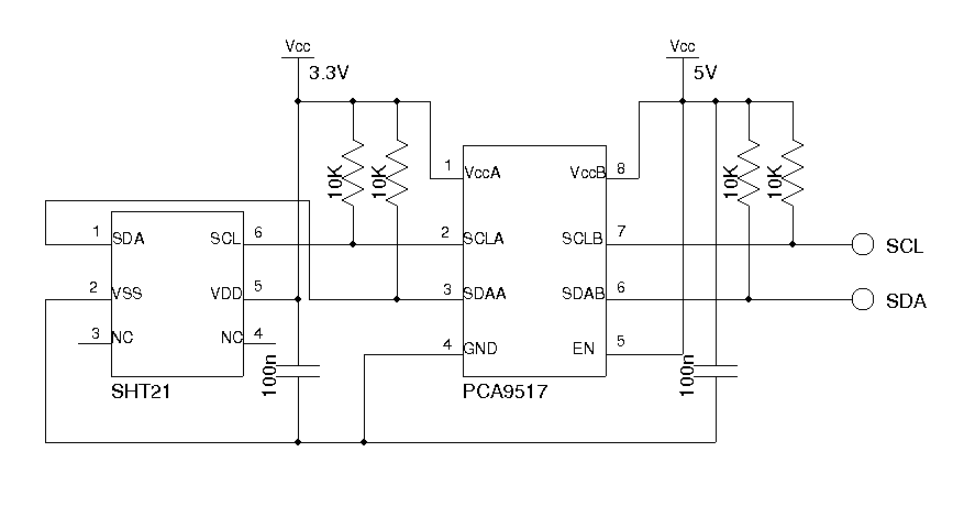
This thermometer employs an LM19 sensor, calibrated to measure a broad temperature range of -55 to 130 degrees Celsius (-67 to 266 degrees Fahrenheit) for outdoor temperature readings. For indoor temperature and humidity measurements, it utilizes an SHT21 digital...
The display interface utilizes the ICM7218A/B in conjunction with an 8048 family microcontroller. An 8-bit data bus (DBO/DB7-IDO/ID7) facilitates the transfer of control and data information to the 7218 display interface during successive WRITE pulses. The mode input pins...
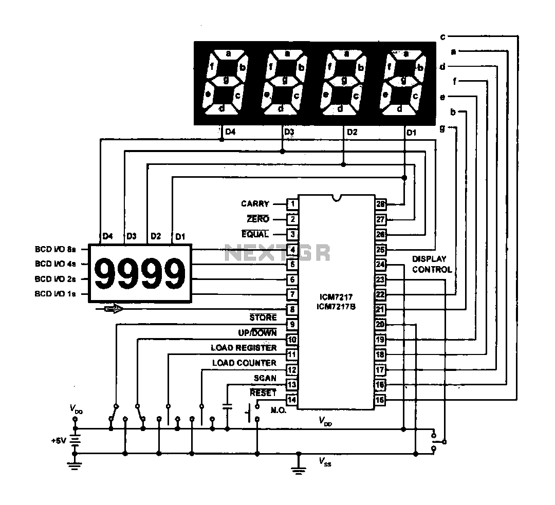
The circuit drives the light-emitting diode in a digital display configuration. The count signal is fed into the ICM7217 chip, which processes the count and subsequently drives the digital display board. The connection between the thumbwheel switches is illustrated...
Warning: include(partials/cookie-banner.php): Failed to open stream: Permission denied in /var/www/html/nextgr/view-circuit.php on line 713
Warning: include(): Failed opening 'partials/cookie-banner.php' for inclusion (include_path='.:/usr/share/php') in /var/www/html/nextgr/view-circuit.php on line 713