
Adding sync pulses to the video signal
The circuit described is a sophisticated solution for generating a composite video output signal suitable for external monitoring applications. It employs a combination of active and passive components to achieve the desired signal quality. The integration of a DC-restorer ensures that the video signal maintains a consistent black level, which is critical for accurate image reproduction. The adjustable resistor RV1 allows for fine-tuning of the video amplitude, accommodating variations in signal strength from different camera sources.
The nonlinear DC-amplifier configuration of IC2, along with the associated diodes and resistors, provides a gamma correction feature that is essential for enhancing image contrast and fidelity. The ability to switch between different gamma settings (gamma = ½ and gamma = 1) allows for flexibility depending on the specific requirements of the display medium or viewer preferences.
The alignment of the photodiode and LED with the sync holes is a crucial aspect of the design, as any misalignment can lead to synchronization issues, affecting the overall performance of the video output. The use of a masking technique to define the light-sensitive area is an effective approach to optimize the sync pulse duration, thereby preventing unnecessary wastage of screen space.
Overall, this circuit serves as a comprehensive solution for composite video output, effectively combining synchronization, signal conditioning, and gamma correction in a single design, making it suitable for a variety of applications in video processing and display technologies.This section contains details for providing a composite video output signal from the camera to drive an external monitor. The circuit described below, designed by Peter Smith, is a combined DC-restorer, switchable gamma corrector and video/sync mixer using a photodiode and LED to sense the 32 holes around the disc`s circum-ference to generate the
required sync pulses. The negative excursion of the video signal from the camera head is clamped to 0. 8 of a volt by the action of the amplifier IC1 and the diode D1. The black level clamp is set by the ratio of R2 to R1. This determines the amplitude of the resulting sync pulses. The amplitude of the video component of the signal is set by RV1. IC2 is configured as a non linear DC-amplifier. Diodes D2 to 4 and resistors R11 to 13 approximate a square root response (gamma = ½). RV1 should be adjusted for 1V pp video out to ensure proper operation of the gamma correction circuit. With the switch to R5 the response is linear (gamma = 1). The strobe pin 8 of the second CA3140 is connected to the output of the photo diode via Q1. The sync hole detector components PD1 and LED1 must be carefully aligned with the sync holes in the disc.
In some cases the duration of the sync pulses obtained by this arrangement may be rather long, leading to a broad sync bar at the bottom of the picture that wastes valuable picture area. Masking the surrounding area of the TIL100 detector `hot spot`, so that the light sensitive area is defined by a small (2mm) hole, can cure this problem.
🔗 External reference
Related Circuits
This function generator IC is specified to work to 20 MHz. So far, this unit works nicely to 50KHz. Since I seldom need signals higher than that, it has taken up a happy home on my workbench and further...
This application note provides insight into how to synchronize multiple high-speed DACs in transmitter applications. This document outlines the techniques and methodologies for synchronizing multiple high-speed Digital-to-Analog Converters (DACs) in various transmitter applications. Synchronization is crucial in systems where multiple...
This chapter shows how to connect an analogue signal to a PIC. An analogue signal is similar to a sine wave and is generally less than 5v (5,000mV) in amplitude. Low-level signals are generally expressed in mV, to make...
.png)
The one-touch turn signal (OTTS) module enhances the functionality of the turn signal lever by adding a mode where a single touch makes the indicators blink for a certain number of times. This behavior is also known as lane...
Although the inputs are differential, the right amplifier has a bias current greater than 800 nA. Therefore, the input coupling capacitor should be considered. It is important to note that the resistance value on the input side should also...
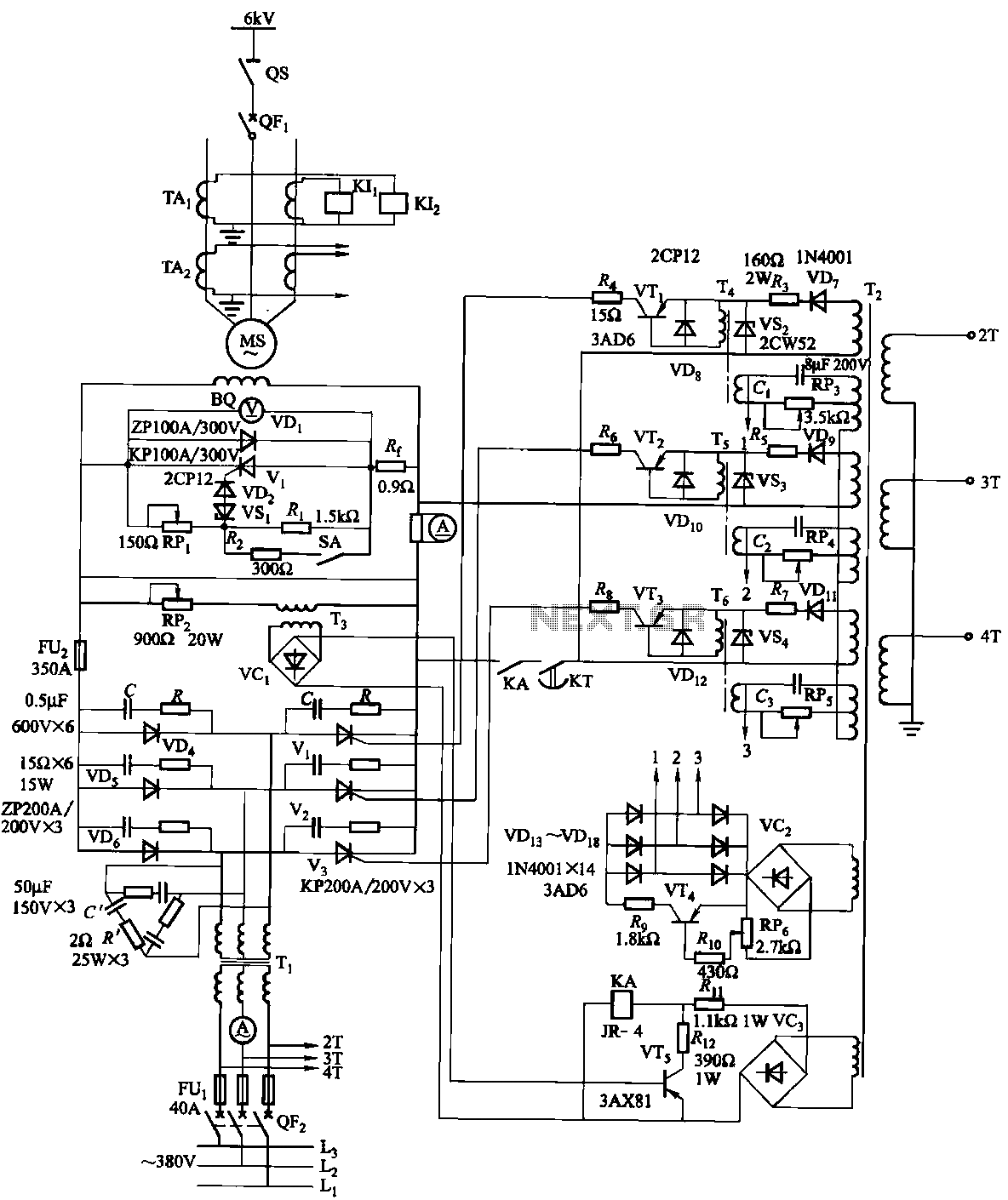
The excitation device for a light-duty synchronous motor rated at 625 kW has been initiated. The triggering circuit of the device consists of three identical RC phase-shift flip-flops. Adjustment potentiometers RP3 to RPs are used to set the RC...