
Adjustable from 3 to 9V 100mA power supply circuit
The power supply circuit operates effectively within the specified voltage and current parameters, making it an excellent choice for applications requiring adjustable low-voltage DC power. The transformer steps down the AC voltage, which is then rectified by the diode bridge (VD1-VD4) to convert it into a pulsating DC voltage. Capacitor C1 smooths out the rectified output, providing a more stable DC input to the regulation section.
The heart of the regulation circuit consists of two transistors, VT1 and VT2. VT1 functions as a variable resistor, adjusting its conduction based on the output voltage requirements. When the output voltage decreases, the voltage drop across VT1 reduces, allowing for increased current flow to maintain the desired output level. Conversely, if the output voltage increases, the voltage drop across VT1 increases, thus regulating the output back to the set point.
VT2 serves to amplify the control signal from a potentiometer, which allows the user to adjust the output voltage. The voltage divider formed by the potentiometer and resistors provides feedback to the base of VT2, ensuring that any fluctuations in output voltage are compensated for. This feedback loop is critical for maintaining a stable output, as it allows the circuit to react dynamically to changes in load conditions.
Diodes VD5 and VD6 are essential for establishing a stable reference voltage for the circuit. Their forward voltage drop creates a fixed voltage level that the regulation circuit can rely on, ensuring consistent performance. The design takes advantage of the characteristics of silicon diodes, which exhibit minimal variation with current changes, thus enhancing the reliability of the voltage reference.
The use of bias resistors and load resistors is crucial for the proper functioning of the transistors. These components help set the operating point of the transistors and ensure that the circuit can handle variations in load without significant drops in output voltage. Capacitor C2 is included to filter any remaining AC ripple, enhancing the overall stability of the power supply.
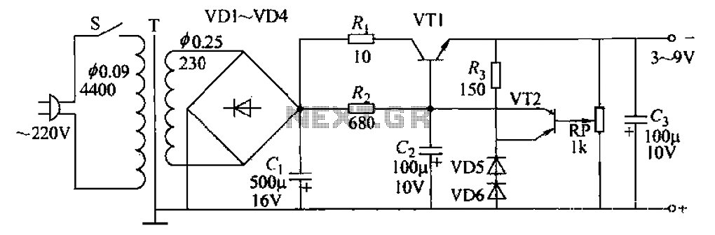
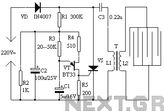
In conclusion, this adjustable power supply circuit is a robust solution for providing low-voltage DC power with a high degree of stability and flexibility. The careful selection of components and the thoughtful design of the feedback mechanism ensure that it can meet the demands of various applications, particularly in powering sensitive electronic devices such as transistor radios.3-9V adjustable lOOmA power supply as shown in Figure 12-30 power supply, there is a series regulator circuit using the amplifier tubes, the output voltage from the 3 ~ 9V cont inuously adjustable output current can reach lOOmA, suitable for power supply voltage transistor radios use a different variety. Circuit principle: low-voltage AC transformer secondary side, through rectifier diode VD1-VD4 rectifier, filter capacitor c1, that DC power supplied to the regulator section.
Regulated in part by the regulator VT1 ,. VTZ amplification and play the role of regulator of silicon dioxide hibiscus tube VD5, VD6 other components. Acronym startling drop tube voltage drop transistor collector and emitter of the plate. Monument tube voltage modulation on takeover VT1 is variable, when the output voltage decreases tendency t voltage drop will automatically become smaller, maintaining constant output voltage when the output voltage tends to increase, and pressure drop automatically become larger, still maintain the output voltage constant.
Visible, VT1 is equivalent to a variable resistor, due to its regulatory effect, so that the output voltage is substantially unchanged. The role of the regulator is adjusted by the amplification VT2 control potentiometer output voltage through the voltage divider, the output voltage is applied to the base part VT2 between the electrode and the ground.
Since launching Xi VT2 ground voltage through - diode VD5, VD6 stable, can be considered VT2 emitter-to-ground voltage is constant, this voltage is called the reference voltage. such. r: r2 base voltage the change is reflected in the output voltage variation rhyme. If the output voltage is reduced (refer to absolute value, the same below) trend, VT2 base emitter voltage should also be reduced, which makes the collector current of VT2 is reduced, the collector voltage increases.
Since VT2 and VT1 is directly coupled Yun, VT2 collector Xi voltage increases, VT1 is the base-emitter voltage is increased, which makes VT1 strengthen conduction voltage drop is reduced to maintain the output voltage constant. Similarly, if the output voltage increasing trend, by the action of the tube drop VT1 VT2 increases, maintain the output voltage constant.
VD5, VD6 is to use them in the forward conduction when the forward voltage drop substantially no current change in the characteristics of the regulator. Silicon tube forward voltage drop of about 0. 7V, two silicon diodes in series can get a stable voltage of approximately 1.4V. Regulators did not take advantage of the positive characteristics of the use of anti- breakdown characteristics to good effect, its advantage is the ability to provide a lower regulated voltage.
The horse is to provide VD5, limiting resistor VD6 forward current. Load resistance Rz is VT2, VT1 is a bias resistor. Ri to the output current is high time to reduce the pressure drop and set VT1 opposed. C2 is taken into account when the mains voltage is reduced in order to reduce the output voltage of the AC component and set up. G is to reduce the role of stable power supply voltage AC resistance and ripple.
Related Circuits
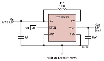
The LTC3525-3/LTC3525-3.3/LTC3525-5 are high-efficiency synchronous step-up DC/DC converters with output disconnect capability that can operate with an input voltage as low as 1V. These converters provide a compact and efficient alternative to charge pumps for single-cell or dual-cell alkaline...
Class D audio power amplifier schematic diagram with TDA7480, capable of 10W output power at a load of 8Ω/4Ω and a total harmonic distortion of 10%. Requires a split-supply (max. ±20V). The Class D audio power amplifier utilizing the TDA7480...
This circuit is housed in a compact enclosure and is positioned within the refrigerator, either near the lamp or at the door opening. When the refrigerator door is closed, the interior remains dark, causing the photoresistor R2 to exhibit...
The objective of this project was to monitor power consumption in a residential setting. In addition to tracking total usage, the goal was to separately monitor and compare the usage of major appliances, such as the water heater, heat...
The electronic fly disinfestation system is a simple and effective device designed to eliminate flies using electrical means. The apparatus, as depicted in Figure 1, operates on 220V mains power supplied directly through a rectifier. It utilizes a relaxation...
In many countries, it is now mandatory or at least recommended to have a rear fog light on a trailer. There is an additional requirement that when the trailer is connected to the vehicle, the rear fog light of...