
Adjustable output MAX761 boost power supply
The MAX761 is a high-efficiency DC-DC boost converter designed to convert a lower input voltage to a higher output voltage while maintaining low power consumption. This device is particularly useful in battery-operated applications where energy efficiency is paramount.
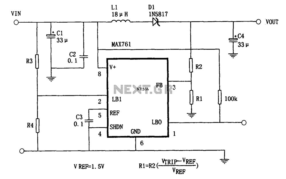
The output voltage (Vo) is adjustable and is set by the external resistors R1 and R2. The formula Vo = VREF (1 + R2/R1) indicates that the output voltage is a function of the reference voltage (VREF), which is fixed at 1.5V in this configuration. The choice of R1 and R2 directly influences the output voltage, allowing for flexibility in design to meet specific voltage requirements.
In practical applications, it is essential to select R1 and R2 with appropriate values to achieve the desired output voltage while ensuring stability and efficiency. The MAX761 operates with a wide input voltage range, making it suitable for various applications including portable devices, sensors, and other low-power electronics.
The circuit typically includes additional components such as input and output capacitors to filter voltage spikes and ensure stable operation. An inductor is also employed to store energy during the switching cycle, which is released to the output during the non-conducting phase, contributing to the boost function.
Overall, the design of this DC-DC converter circuit exemplifies a compact and efficient solution for applications requiring adjustable output voltage with minimal power loss. As shown in FIG grounds efficient, low-power output voltage boost DC-DC converter MAX761 and a few external components, the adjustable power conversion. Its output voltage is d etermined by the ratio of R1 and R2, according to the formula Vo (1 + R2/Rl) VREF calculated, VREF 1.5V.
Related Circuits
The first application has to be a stereo power amp, since that's what I built using two prototype modules. The reasons for this choice are twofold - a good high powered stereo amp is always useful, and it was important...
This circuit is designed to charge NiCd or NiMH batteries using solar cells. It maximizes power extraction from a solar array to charge a battery stack. The circuit utilizes the MAX856 boost converter and the MAX982 dual comparator with...
This article addresses inquiries regarding a low-power FM transmitter designed to accept input from various sound sources, such as a guitar or microphone, and transmit on the commercial FM band. It is important to select an unused frequency on...
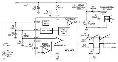
A temperature-controlled pulse-width-modulator (PWM) boost converter circuit diagram is illustrated in the following figure. This boost converter is designed to operate a 12V fan using a 5V supply while maintaining temperature control. The temperature-controlled PWM boost converter circuit operates by...
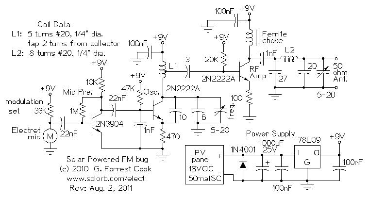
Numerous miniature FM transmitter bug circuits are available online; however, this particular design is distinctive as it operates entirely on solar power, eliminating the need for a battery. The transmitter will function as long as sunlight is incident on...
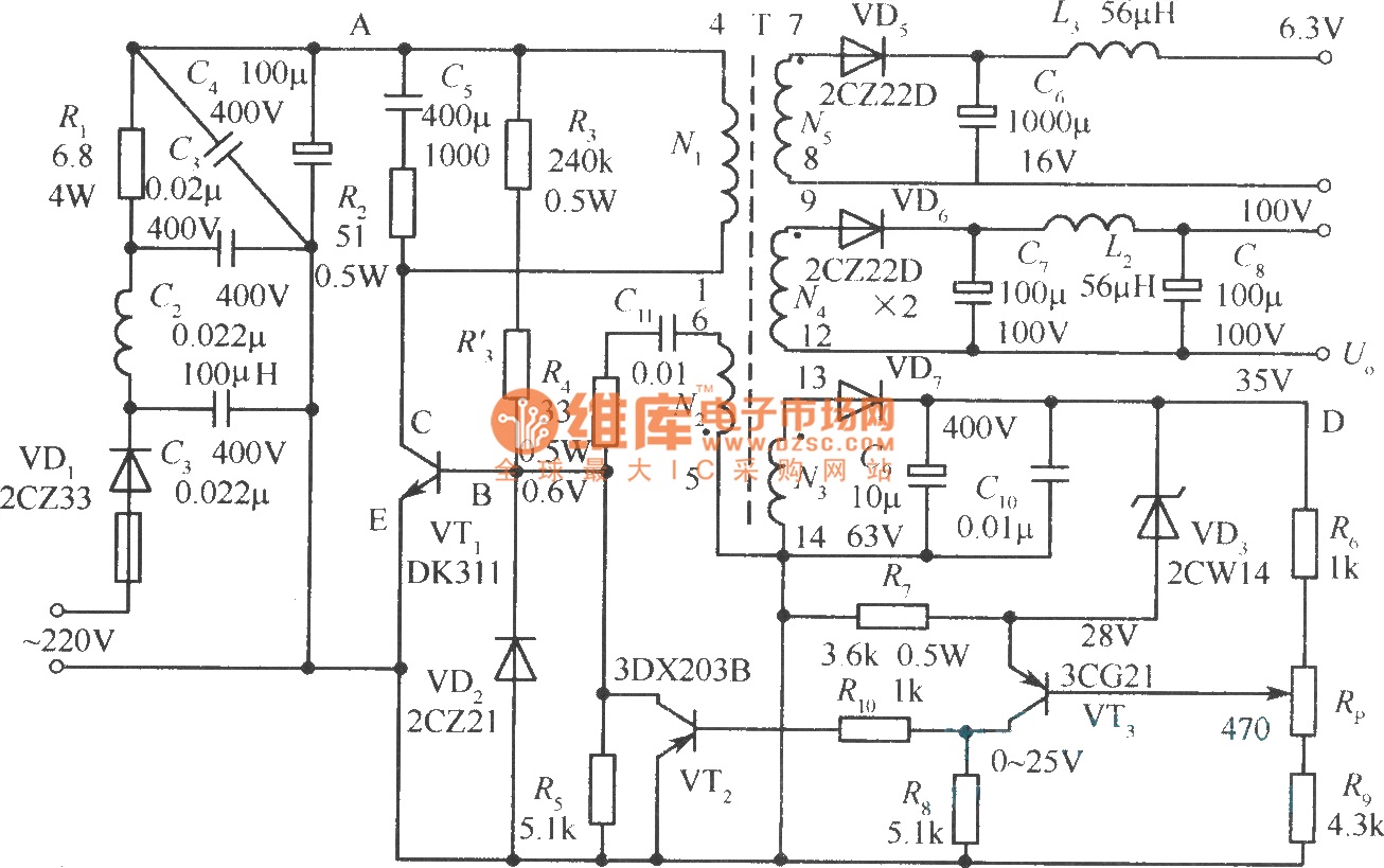
The diagram illustrates the output sampling winding of an isolated switching power supply. In the diagram, T represents a high-frequency transformer; N2 denotes the self-oscillation positive feedback winding; N3 is the error amplifier; VTS is the winding that provides...