
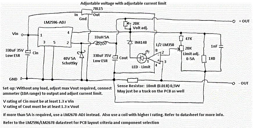
Adjustable voltage with adjustable current limit circuit
The circuit design and implementation of a CNC (Computer Numerical Control) system, such as that of the Boxford 125 TCL CNC Lathe, involves a variety of components and subsystems that work together to achieve precise control over mechanical operations. The core of the system typically includes a microcontroller or a dedicated CNC controller board that interprets G-code commands, which are generated by CAD/CAM software.
The CNC controller interfaces with stepper motors or servo motors that drive the lathe's axes. Each motor is connected to a motor driver circuit, which amplifies the control signals from the microcontroller to provide sufficient current and voltage to drive the motors. The choice between stepper and servo motors depends on the required precision and the load characteristics of the application.
Power supply design is critical in ensuring that the CNC system operates reliably. It must provide stable voltage and current to all components, particularly during peak loads when the motors are under heavy torque. Filtering capacitors and voltage regulators are often employed to smooth out power supply fluctuations.
Feedback systems, such as encoders or limit switches, are also integral to the CNC lathe design. Encoders provide position feedback to the controller, allowing for closed-loop control, which enhances accuracy and repeatability. Limit switches are used to prevent the machine from exceeding its physical limits, thereby protecting both the machine and the workpiece.
The software aspect of the CNC system involves not only the firmware running on the microcontroller but also the user interface that allows operators to input commands and monitor the machine's status. This may include real-time display of motor positions, speed settings, and error messages.
Overall, the design of a CNC lathe system is a complex interplay of hardware and software, requiring careful consideration of electrical, mechanical, and programming elements to achieve the desired performance and reliability.This site is primarily for me to collect together things that I find useful that I don`t want to forget but occasionally I may put together some pages that others may find interesting. Please have a browse and see what you can find. I tried to make the effort to document my retrofit of the Boxford 125 TCL CNC Lathe. It`s horribly out of date as I `ve now refitted the machine again but someone may find it interesting. I like to watch machines seemingly working by themselves being controlled by a computer. That`s why I`ve played around with a couple of CNC machines. Take a look at these machines: I make a living writing software for McAfee. I don`t work on the antivirus products, I work on Endpoint Encryption which provides full disk encryption services. My work generally involves either writing preboot code (before the operating system starts) or drivers and the like for PCs running Windows and Linux as well as for the Mac, which I`m currently working on.
This means I spend most of my time writing low level code in C and assembler. Exactly what I like doing! As well as writing software for work, I quite often start my own projects at home, normally just for fun or to make something that is useful to me (but not normally to anyone else!). These projects normally run on some sort of PC platform but occasionally spill onto some custom hardware such as a PIC microcontroller.
In this section you will find snippets of information that I have been collecting that I don`t want to forget. You may find something useful here but I doubt it. 🔗 External reference
Related Circuits
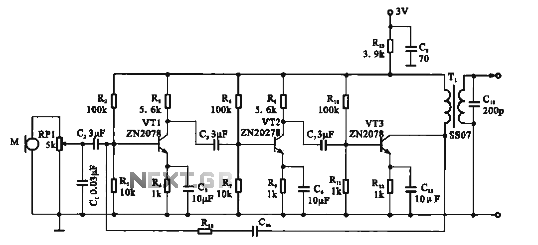
This circuit is a recording signal amplifying transistor circuit that illustrates the functioning of a microphone signal amplifier. After adjustment through potentiometer RP1, the signal is applied to the transistor VT1, which operates as a common emitter amplifier. The...
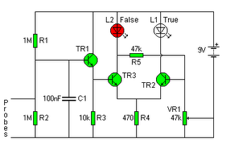
The following circuit illustrates a Lie Detector Circuit Diagram. Features include a capacitor that eliminates the 50Hz induced mains hum present in the circuit. The Lie Detector Circuit operates on the principle of measuring physiological responses, typically galvanic skin response...
For individuals who prefer not to engage directly with soil, this simple soil moisture tester efficiently assesses the condition of their plants and the level of care they require. The soil moisture tester is a device designed to measure the...
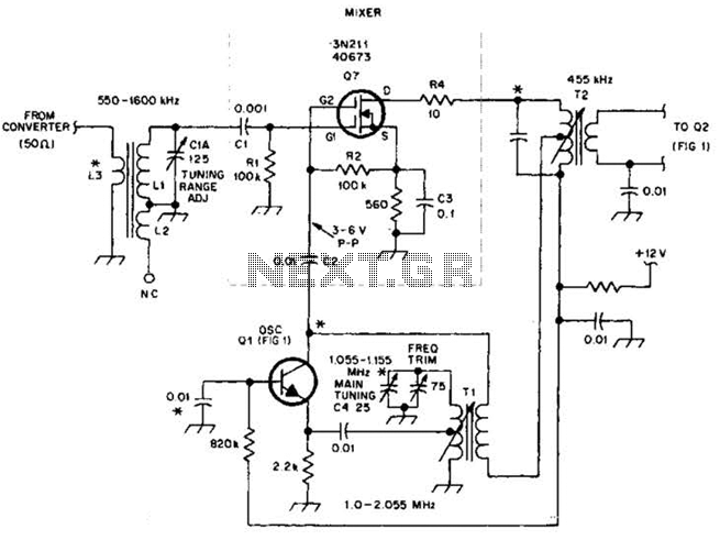
This circuit is an enhanced front end for upgrading a transistor AM receiver. This front end is beneficial when the radio is intended to function as a tunable IF amplifier with shortwave converters. The circuit described serves as a sophisticated...
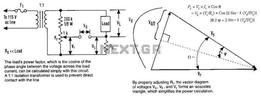
The load's power factor, defined as the cosine of the phase angle between the voltage across the load and the load current, can be calculated using this circuit. An isolation transformer with a 1:1 ratio is employed to prevent...
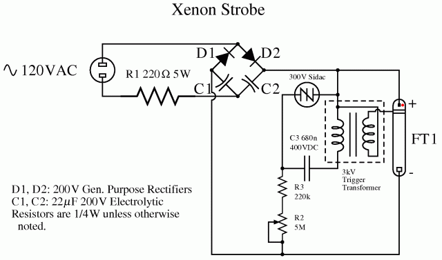
Xenon lamp, strobe light circuits, xenon strobe, photo flash, photoflash, schematics or diagrams, all free to use. The inspiration originated from a strobe circuit that was part of a school fire alarm. Xenon lamps are high-intensity discharge lamps that emit...