
advanced bicycle lighting Schematic
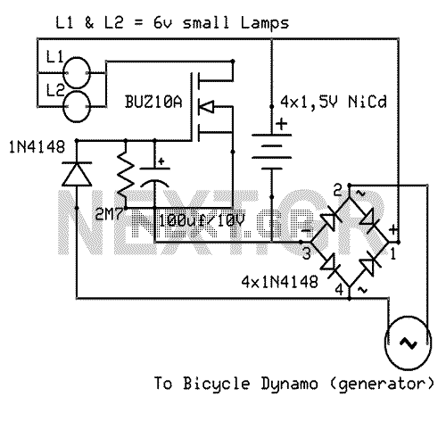
The advanced bicycle lighting system described operates on a principle of energy generation and storage, ensuring that bicycle lights remain functional during both motion and stationary periods. The system utilizes a dynamo or a similar energy harvesting device that is mechanically linked to the bicycle's wheel. As the bicycle moves, the dynamo converts kinetic energy into electrical energy, which is then used to power the LED lights.
The charging mechanism for the four nickel-cadmium (NiCd) batteries is integrated into the circuit. The electrical output from the dynamo is rectified using a diode bridge to convert the alternating current (AC) produced by the dynamo into direct current (DC), suitable for charging the batteries. A charge controller circuit is essential to manage the charging process, preventing overcharging and ensuring the longevity of the NiCd batteries.
The system is designed to operate automatically, eliminating the need for manual switches. This is achieved through a combination of voltage sensing and a relay or transistor-based control mechanism that activates the lighting system when the bicycle is in motion and continues to draw power from the batteries when stationary.
The absence of a printed circuit board (PCB) suggests that the components may be assembled using a point-to-point wiring technique or mounted on a breadboard, which allows for flexibility in the design and easy modification or troubleshooting.
Overall, this bicycle lighting system exemplifies an efficient and sustainable approach to maintaining visibility and safety for cyclists, leveraging the principles of renewable energy and automated control.That Circuit is an advanced bicycle lighting system which will power your lights and also charge four NiCd batteries while you running in the streets, for keeping the lights on while the bicycle is stoped. Its fully automated without any switches. You can not even use any PCB for that circuit. 🔗 External reference
Related Circuits
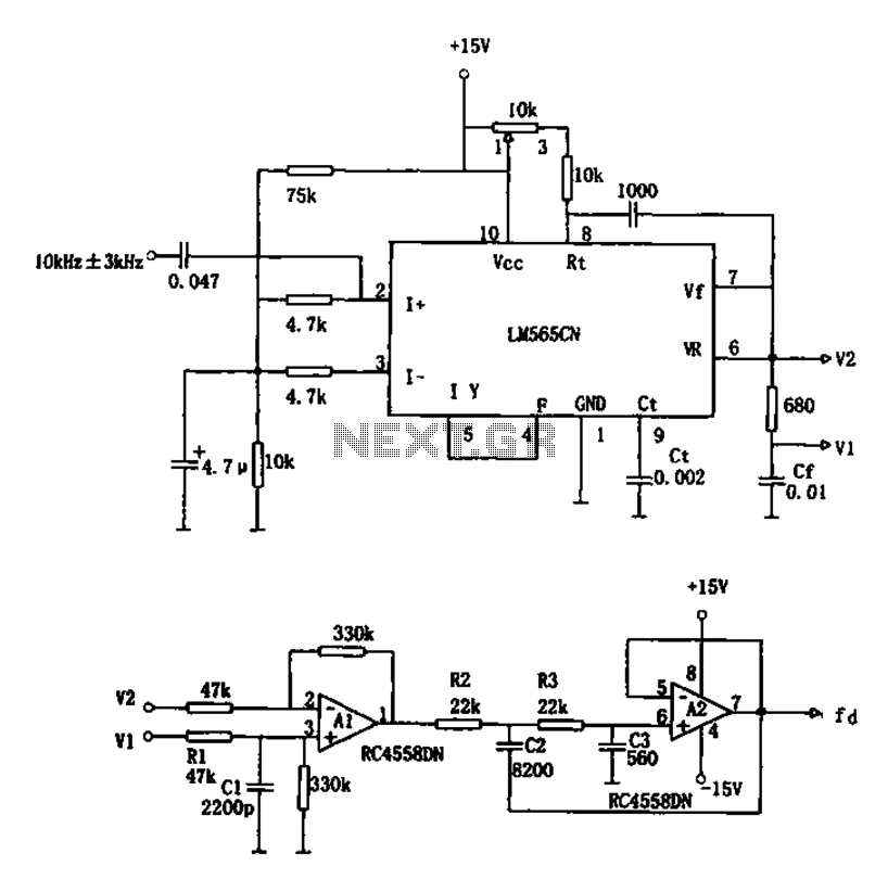
The circuit utilizes a 10 kHz and 3 kHz LM565CN to create an FM demodulation setup. The output diagram (b) illustrates the differential demodulation outputs V1 and V2 from the differential amplifier A1, which provides level displacement and amplification....
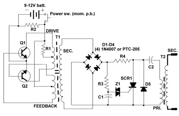
Three schematics are available for individuals interested in constructing their own stun gun. For those familiar with reading electronic schematics, the three stun gun circuits presented on this page contain all the necessary information to build a stun gun....
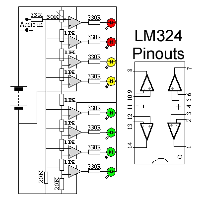
This circuit utilizes two quad op-amps to create an eight LED audio level meter. The op-amp employed in this circuit is the LM324, a widely used integrated circuit that is readily available from numerous electronic component suppliers. The 1K...
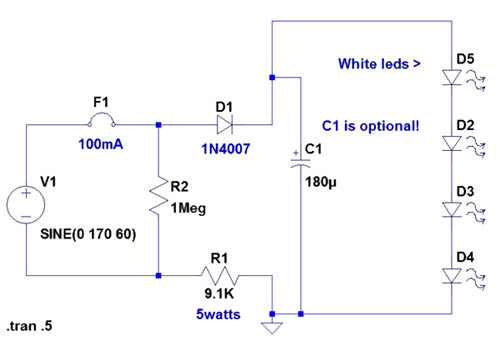
If the AC supply is 220 volts, which resistor should be replaced and with which one? Since 220V is twice that of 110V, the resistance value needs to be doubled accordingly. It is suggested to replace the 9.1kΩ resistor...
Approximately 20 years ago, it was common to encounter small key-holders that emitted an intermittent beep for a few seconds after the owner whistled. These devices utilized a specialized integrated circuit (IC) and were not suitable for home construction....
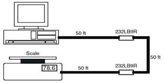
This is the schematic diagram of a 9-Pin RS232 Line Booster Signal Direction. The device functions as a 9-pin RS-232 repeater, re-transmitting all 8 signals while also maintaining the ground line. The 9-Pin RS232 Line Booster is designed to extend...