
Advanced Phone in use circuit
This project implements a dual-phone line status indicator using a combination of series and parallel configurations to effectively monitor the state of two phones connected to the same line. The circuit utilizes two types of LEDs to indicate the status of each phone: a green LED for the primary phone and a red LED for the extension. The design addresses the challenge of detecting the presence of an extension phone while ensuring adequate LED brightness, which is typically compromised when using the phone line's limited voltage and current capacity.
The circuit begins with a voltage divider network consisting of resistors (1M, 470k, and 100k) that biases the base of a PNP transistor (BC557). Under normal conditions, when both phones are on-hook, the line voltage remains high (approximately 50V), keeping the transistor in the off state and the LEDs unlit. When either phone is lifted, the line voltage drops, which is detected by the circuit, turning on the green LED.
The series bridge configuration, which includes a 220-ohm load resistor, plays a crucial role in detecting the extension phone. When the primary phone is lifted, the voltage across the 220-ohm resistor generates a turn-off voltage that keeps the red LED off. However, when the extension phone is lifted, the voltage drop across the resistor allows the red LED to illuminate, indicating the extension is in use.
Power consumption is optimized by utilizing a 3V battery that only activates when a phone is lifted, ensuring long operational life. The circuit's design allows for troubleshooting through various test points, ensuring that any issues with LED illumination or transistor switching can be effectively diagnosed. The system is designed to maintain low current draw during idle states, with typical operating currents of 4mA for the green LED and 6mA when both LEDs are illuminated. Overall, this project provides an effective solution for monitoring phone line usage, enhancing communication without the risk of interruptions.This project has two features. It will let you know when a single phone is using the line and also when two phones are on the line! The green LED indicates the first phone and the red LED indicates the second phone! There are many times when you need to know the state of the phone line and this project will prove to be invaluable. It will prevent you picking up the phone when the extension is being used but most important it will indicate when the extension has been picked up when you are on the line.
In some cases the extension will make no difference to the sound level on the main handset and the extension party can listen in without being detected. There are quite a number of PHONE ALERT products on the market and although I have not seen them all, the ones I have tested failed to work. They failed because no one has ever tried them! The phone system is much more complex than you think and when a mechanical and electronic phone is connected to the same line (the same two wires), it is not possible to detect the electronic phone when the mechanical is in use.
The reason is the mechanical phone drops the line voltage to about 3-5v while the electronic phone drops the line voltage to about 15v. (when they are on the line separately). This means they are different impedances (different resistance) and when they are on the line at the same time, the electronic phone drops the line voltage only about a further .5v over that of the mechanical phone.
This is a very small change and since the voltage across the mechanical phone is not always the same, there is no way of setting a detection point. It is not possible to detect the extension by using a series LED or parallel LED to cover all the possible combinations where the detection unit is placed with respect to the high and low impedance phones.
Furthermore, any circuit using the phone line to drive the indicator LEDs will result in very poor brightness as the line does not have enough energy in reserve, when the phone is being used. With a mechanical phone there is only about 3-5v available and you can only draw about 1mA in parallel mode.
Even with a flasher chip the effect is less than acceptable. In the series mode you cannot detect the extension phone unless the main phone is picked up and so a simple series or parallel mode will not work. What is needed is a combination of both parallel and series and after a lot of experimenting, this project solves the problem.
One of the first things we realized is the need for a 3v supply to give the LEDs the brightness they need - using the phone line is useless. Power is only consumed from the battery when the handset is lifted and the battery will last many hundreds of hours.
The clever part of the circuit is the use of both series/parallel bridges. The parallel arrangement is easy to understand. It detects a drop in line voltage when either phone is lifted, and causes the green LED to turn ON. When both phones are on hook, the line voltage is about 50v and a voltage divider made up of the 1M, 470k & 100k, reverse biases the base of the BC 557. This keeps the transistor switched off and the LED is not illuminated. When the line voltage falls, the base voltage is pulled lower than 3v (actually 2.35v) by the 100k and thus the transistor is turned on.
Now we come to the clever part of the circuit. Connected between the phone and the exchange is a SERIES BRIDGE with a 220R load resistor. When the "home" phone is lifted, it puts a voltage across the 220R so that a "turn off" voltage is still generated on the base of the second BC 557 to keep the red LED off. When the extension is lifted, the voltage falls away and the red LED turns ON. The effect of the 220R is to multiply the voltage drop caused by the extension phone, to about 2v and now we can reliably detect the extension being picked up.
IF IT DOESN'T WORK The tee piece is NOT connected to the phone line for these tests. If the LEDs do not come on, or if one LED doesn't come on, the most probable cause is a damaged LED due to soldering or a reverse-biased LED. Try the LED(s) around the other way or a new LED. They can be easily damaged by too much heat and if this is the case, they will lose their brightness.
If one or both LEDs still do not come on, short between collector and emitter of each transistor and if the associated LED turns ON, the transistor is not switching. This may be due to the base voltage not being low enough or the transistor being damaged. To test the transistor put a 1k resistor between base and negative to force the transistor to turn ON.
If this is successful, you should remove the 1M resistor from the parallel bridge to see why the base is not turning on. The only possible explanation is an open connection to the base and you should look at the track-work.
The same applies to the second LED. Remove the 1M mini trim pot and check the circuit. A fault must be present that is preventing the base turning the transistor ON. In other words the base is not going lower than 2.5v. Don't forget, we are using PNP transistors and when the base falls to 2.35v, the base-emitter voltage is .65v and the transistor turns ON. If the base is 2.5v, the base-emitter voltage is .5v and the transistor will not be turned ON. With both handsets "on hook," connect the tee piece to the phone line and both LEDs will go out. If not, a fault will exist in the biasing network. To test the green LED section you will need a good quality multimeter such as 30k ohms/volt or greater as the voltages we are measuring are high impedance.
Make sure all the components are fitted, especially after experimenting, and measure the voltage between the negative rail and base. It should be 3.5v and if the green LED does not turn off fully, the 1M can be reduced to 470k or even lower.
When this section is working, go to the red LED. The same applies to the base of this transistor. The voltage should be higher than the positive rail and may be as high as 9v when the handsets are on the hook. If this voltage is not present, either the transistor is faulty or a leak exists on the board that is preventing the voltage from appearing.
When the "home" phone is lifted, the line voltage drops and the green LED turns ON as the "turn off" voltage disappears and the 100k pulls the base towards the negative rail. But the red LED does not turn ON due to the series bridge creating a different effect. This time the voltage appearing across the 220R adds a few extra volts to that appearing across the home phone and prevents the red LED from illuminating.
You should measure the voltage across the 220R. It should be between 3-5v, depending on the type of phone in use. When the extension is picked up, this voltage drops 2v and the line voltage drops about .5v, making a total of 2.5v, removing the "turn off" voltage and the red LED comes ON. The current consumption from the 3v supply will help in diagnosing any further problems you have. When the project is at rest, the current is zero. When the green LED is on, the current is 4mA. When both LEDs are ON, the current is about 6mA. 🔗 External reference
Related Circuits
The circuit illustrated in Figure 2-49 is straightforward, featuring a cold Positive Temperature Coefficient (PTC) thermistor element. It utilizes the thermal resistance characteristics of the lamp to manage the delay time, which typically ranges from 10 to 30 seconds....
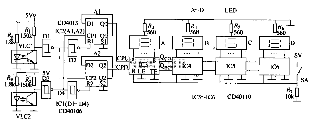
This document describes an electronic winding machine with manual, electric, and semi-automatic features. The specific example highlighted includes an electronic counting function that assists users in managing motor windings. The circuit design consists of various components as illustrated in...
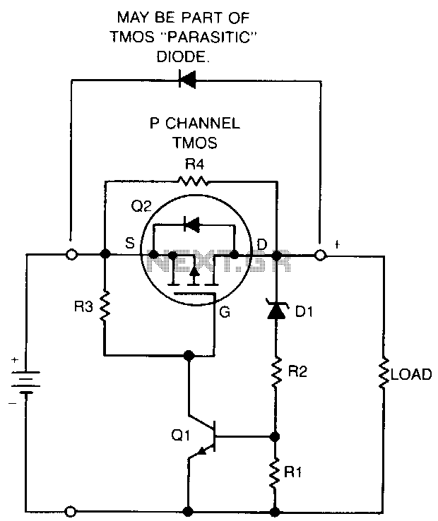
If a NiCad battery is discharged to the point where the lowest capacity cell becomes fully discharged and reverses polarity, that cell will typically short internally and become unusable. To prevent this type of damage, this circuit detects a...

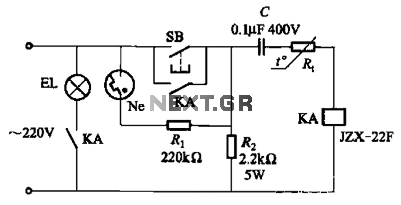
The thermostat electric circuit operates as depicted in the figure. It has three settings: off, low power (Lo), and high power (Peru HL). When the DIP switch SA is set to the Lo position, 220V AC is directed through...
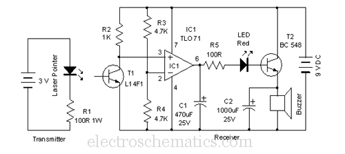
This laser door alarm operates by detecting the interruption of a laser beam. A low-cost laser pointer serves as the light source. When an individual crosses the path of the laser beam, it triggers the alarm. The laser door alarm...
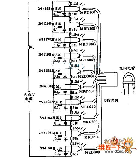
Light emitted by a Xenon flash tube is transmitted to the phototransistor MRD300 through an optical fiber. The sensitive current is amplified to trigger a series of thyristors simultaneously. Consequently, a high voltage of 6000V is applied to loader...