
Advanced Volume control
The described circuit utilizes the DS1669 integrated circuit, which serves as an electronic volume control solution, effectively replacing traditional mechanical potentiometers. The operation is facilitated by two push-to-on switches, S1 and S2, which manage the volume levels for both stereo channels. Switch S1 is designated for increasing the volume, while S2 is responsible for decreasing it.
The DS1669 IC is notable for its electronic interface, allowing for both manual and digital control of the volume settings. This feature enhances the user experience by providing flexibility in operation. The circuit is designed to operate within a wide input voltage range of 4.5V to 8V, making it adaptable to various power supply configurations.
One significant advantage of this circuit is its ability to maintain the wiper position even when power is lost, which ensures that the last volume setting is preserved. This is particularly beneficial in applications where consistent user experience is crucial, such as in audio equipment.
The simplicity and compactness of the circuit are highlighted by the minimal number of external components required, making it a cost-effective alternative to mechanical controls. The applications extend beyond just volume control; it can also be utilized for adjusting tone, contrast, brightness, and dimmer functions in various electronic devices.
Overall, this electronic volume control circuit represents an efficient solution for modern audio applications, enhancing functionality while reducing the complexity associated with mechanical components.This circuit could be used for replacing your manual volume control in a stereo amplifier. In this circuit, push-to-on switch S1 controls the forward (volume increase) operation of both channels while a similar switch S2 controls reverse (volume decrease) operation of both channels. A readily available IC from Dallas semiconductor, DS1669 is used here. FEATURES: Replaces mechanical variable resistors Electronic interface provided for digital as well as manual control Wide differential input voltage range between 4.5 and 8 volts Wiper position is maintained in the absence of power Low-cost alternative to mechanical controls Applications include volume, tone, contrast,brightness, and dimmer control The circuit is extremely simple and compact requiring very few external components. The power supply can vary from 4.5V to 8V. 🔗 External reference
Related Circuits

This device functions as a convenient tool for testing infrared (IR) remote control transmitters used with televisions, VCRs, and similar devices. The IR signals emitted from a remote control are detected by the IR sensor module within the tester,...
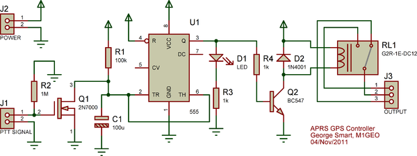
The Yaesu FT-7900E radio's power status can be utilized to manage the power status of the GPS and Tracker without requiring additional cabling. If implemented correctly, this would enable the radio's Auto-Power-Off feature to also turn off the GPS...
Here is a circuit for using the printer port of a PC for control application using software and some interface hardware. The interface circuit along with the given software can be used with the printer port of any PC...
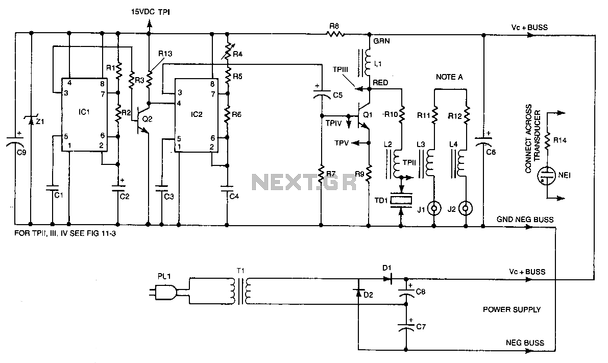
IC2 is a stable oscillator whose frequency and pulse width are determined by the values of R4, R5, R6, and C4. R4 is adjustable for precise frequency setting. The output from IC2 is at pin 3, which is capacitively...
A circuit designed to extract and measure the modulated carrier signal from an infrared (IR) remote control. This circuit does not physically separate control pulses from modulation; instead, it amplifies the complete received signal, allowing the waveform to be...
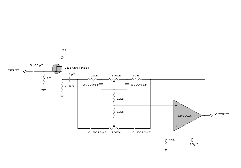
This circuit is a simple series tone control circuit. It utilizes the surgical amplifier LM301A. The JFET 2N3684 provides high input impedance and low noise for the unbuffered operational amplifier, which operates in an equalizer (EQ) configuration. Further details...
Warning: include(partials/cookie-banner.php): Failed to open stream: Permission denied in /var/www/html/nextgr/view-circuit.php on line 713
Warning: include(): Failed opening 'partials/cookie-banner.php' for inclusion (include_path='.:/usr/share/php') in /var/www/html/nextgr/view-circuit.php on line 713