AM Transmitter

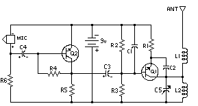
The following diagram is the schematic diagram of a four-transistor FM transmitter circuit designed by Paul K. Sherby. Components List: R1, R2, R8 = 1K, R3 = 100K, R4 = 150K, R5, R7 = 10K, R6 = 220 ohm, R9 = 10 ohm, P1 = 5K trimpot, D1 = 1N4002, Q1, Q2 = 2N3904, Q3, Q4 = 7001, NTE123AP, C1. This transmitter circuit is based on the IC BEL1895. This particular transmitter operates in the shortwave HF band (6 MHz to 15 MHz) and can be utilized for short-range communication and educational purposes. The circuit comprises a microphone amplifier circuit, a variable frequency oscillator, and modulation amplifier stages. Transistor T1 (BF195) is part of the design. The shortwave AM transmitter circuit design diagram is straightforward and easy to construct since it utilizes only a few electronic components. A primary feature of this transmitter is that it is completely free from LC (inductor, capacitor) tuned circuits and operates at a fixed frequency of 12 MHz. This circuit is a powerful three-stage, 9V FM transmitter (Tx) with a range of up to 1 kilometer in open space. It employs an RF transistor in its output stage and two BC547 transistors for the first two stages. The transmission distance is critically dependent on the operating conditions (whether indoors or outdoors). This FM transmitter circuit incorporates four radio frequency stages: a VHF oscillator designed around transistor BF494 (T1), a preamplifier designed around transistor BF200 (T2), a driver designed around transistor 2N2219 (T3), and a power amplifier designed around transistor 2N3866 (T4). A condenser microphone is connected at the input.
The schematic diagram of the four-transistor FM transmitter designed by Paul K. Sherby showcases a compact and efficient design suitable for various applications, including educational projects and short-range communications. The circuit operates within the HF band, providing a frequency range of 6 MHz to 15 MHz, making it ideal for shortwave transmission.
The components used in the circuit are carefully selected to ensure optimal performance. Resistors R1, R2, and R8 are all rated at 1K ohms, providing necessary biasing for the transistors. The variable resistor P1, a 5K trimpot, allows for fine-tuning of the circuit, enhancing flexibility in operation. The use of transistors such as 2N3904 for Q1 and Q2 ensures reliable amplification, while the 7001 and NTE123AP transistors provide additional functionality for modulation and signal processing.
The design includes a microphone amplifier circuit that captures audio signals and converts them into electrical signals suitable for modulation. The variable frequency oscillator generates the carrier wave, which is modulated by the audio signal from the microphone. The modulation amplifier stages enhance the modulated signal before transmission.
In addition to its straightforward design, the FM transmitter circuit operates at a fixed frequency of 12 MHz, eliminating the need for complex LC tuning circuits. This feature simplifies construction and enhances reliability. The three-stage design allows for significant amplification, with the output stage utilizing an RF transistor capable of delivering sufficient power for transmission over distances of up to one kilometer in open conditions.
The four radio frequency stages of the circuit, including the VHF oscillator, preamplifier, driver, and power amplifier, work in concert to produce a stable and powerful output. The BF494 transistor serves as the VHF oscillator, while the BF200 is utilized in the preamplifier stage, ensuring that audio signals are effectively amplified before further processing. The 2N2219 transistor acts as the driver, providing additional gain, while the 2N3866 serves as the power amplifier, delivering the final output signal.
Overall, this schematic diagram represents a well-thought-out design that balances simplicity and performance, making it an excellent choice for hobbyists and educators interested in exploring the fundamentals of FM transmission.The following diagram is the schematic diagram of 4 transistors FM transmitter circuit designed by Paul K. Sherby. Components List: R1, R2, R8 = 1K R3 = 100K R4 = 150K R5, R7 = 10K R6 = 220 ohm R9 = 10 ohm P1 = 5K trimpot D1 = 1N4002 Q1, Q2 = 2N3904 Q3, Q4 = 7001, NTE123AP C1.
Here the SW transmitter circuit based on IC BEL1895. This particular transm itter circuit works in shortwave HF band (6 MHz to 15 MHz), and can be applied for shortrange communication and for educational purposes. The circuit is composed of a mic amplifier circuit, a variable frequency oscillator, and modulation amplifier stages.
Transistor T1 (BF195) is. Here the short wave AM Transmitter circuit design diagram. The circuit is quite simple and easy to build since it applies only a few electronic components. The primary feature of this transmitter is that it really is absolutely free from the LC (inductor, capacitor) tuned circuit and runs using a fixed frequency of 12 MHz. This circuit is a powerful three stage, 9V FM transmitter (Tx) with a range of up to 1 kilometer in the open.
It uses an RF transistor in its output stage and two BC547`s for the first two stages. Distance of trans-mission is critically dependent on the operating Conditions (in a building or out on. This is the FM transmitter circuit which apply 4 radio frequency stages, that are a VHF oscillator designed around transistor BF494 (T1), a preamplifier designed around transistor BF200 (T2), a driver designed around transistor 2N2219 (T3) and also a power amplifier designed around transistor 2N3866 (T4).
A condenser microphone is wired at the input of. 🔗 External reference
Warning: include(partials/cookie-banner.php): Failed to open stream: Permission denied in /var/www/html/nextgr/view-circuit.php on line 713
Warning: include(): Failed opening 'partials/cookie-banner.php' for inclusion (include_path='.:/usr/share/php') in /var/www/html/nextgr/view-circuit.php on line 713


