
AM Transmitter
An AM transmitter is designed to modulate an audio signal onto a carrier wave for the purpose of broadcasting. The operation of the transmitter involves several key components: an audio input stage, a modulator, an oscillator, and an output stage.
The audio input stage typically consists of a microphone or audio source connected to an amplifier that boosts the audio signal to a suitable level for modulation. The modulator combines the audio signal with a high-frequency carrier wave generated by the oscillator. This carrier wave is usually generated using a crystal oscillator or a LC circuit, which provides stability and precision in frequency.
The modulation process involves varying the amplitude of the carrier wave in accordance with the audio signal. This is achieved using a transistor or a dedicated modulation IC, which allows the audio signal to control the amplitude of the carrier wave effectively.
The output stage is responsible for driving the antenna. In this circuit, the power output is intentionally limited to comply with legal restrictions and to reduce interference with other communications. This is often accomplished through the use of resistors or limiting circuits that prevent excessive power from being transmitted.
The antenna itself is typically a simple wire or dipole design, tuned to the frequency of the transmitter to ensure optimal radiation of the signal. Proper grounding and matching of the antenna to the transmitter circuit are essential for efficient transmission.
It is crucial to emphasize that operating an AM transmitter without the appropriate licensing can result in legal penalties. Therefore, it is recommended that individuals interested in building or operating such transmitters familiarize themselves with local regulations and obtain the necessary permits.AM Transmitter. It is illegal to operate a radio transmitter without a license in most countries. This ircuit is deliberately limited in power output but. 🔗 External reference
Related Circuits
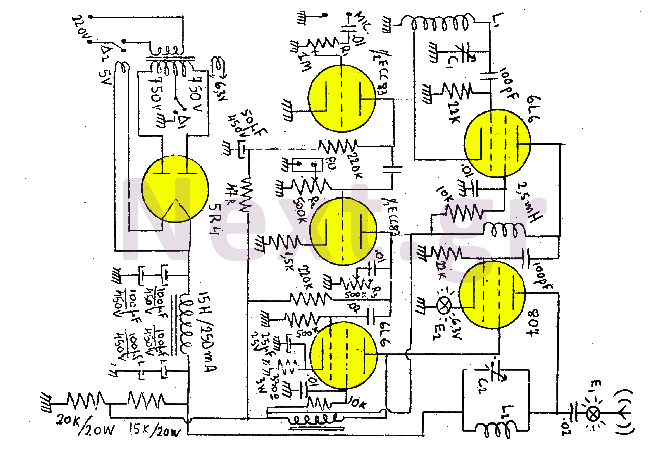
This transmitter consists of a total of five bulbs. The 6L6 tube functions as an oscillator, directing oscillations to the grid of the 807 tube, which serves as the final amplifier and the transmitter output lamp. The amplifier includes...

This circuit diagram is part of an RF circuit. It features an FM transmitter circuit diagram using the BH1417 integrated circuit from RHOM, which incorporates multiple functionalities in a compact design. The IC includes pre-emphasis and a limiter to...
The Muntz one-tube design can be significantly enhanced by incorporating an audio preamplifier stage. This modification increases sensitivity, allowing for full modulation with lower-level signal sources, such as certain older CD players and ceramic phono cartridges. Additionally, implementing negative...
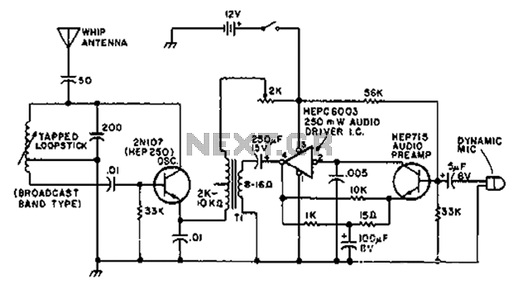
A circuit diagram of the T1 is a low-impedance output transformer, featuring a 5000-8 ohm resistor. The T1 low-impedance output transformer is designed to match the output of audio amplifiers to the impedance of loudspeakers, ensuring optimal power transfer and...
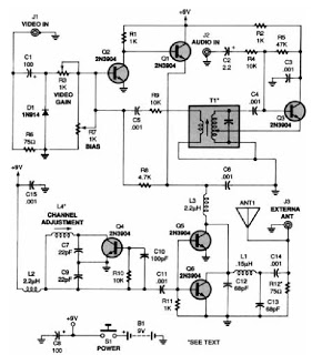
A low-power VHF TV transmitter is an essential tool for video enthusiasts, allowing the transmission of signals from a VCR to any television in a home or backyard setting. This device enables the convenience of watching movies by the...
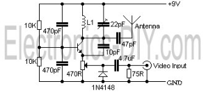
The video transmissions from this unit can be received on a small portable, tunable, and battery-operated TV set, similar to those found in flea markets. The described unit is capable of transmitting video signals that can be captured by compact,...