
Amplifier Cool-Down Circuit Circuit

The cool-down relay circuit is designed to enhance the operational efficiency of systems requiring a cooling period after shutdown, such as HVAC systems or industrial equipment. The core component, timer U3, typically configured as a monostable multivibrator, generates a pulse that activates the relay upon receiving a trigger signal.
The relay acts as a switch that keeps the blower motor operational for a predetermined time, ensuring that residual heat is effectively dissipated from the system. The time delay is primarily influenced by the values of the timing capacitor (C2) and the timing resistor (R1), which work in conjunction with the timer's internal circuitry. By altering the capacitance of C2, one can fine-tune the delay period to meet specific cooling requirements.
The circuit may also include additional components such as diodes for flyback protection, ensuring that the relay coil does not generate voltage spikes that could damage the timer or other sensitive components. A power supply circuit is necessary to provide the appropriate voltage levels for the timer and relay operation.
In summary, this cool-down relay circuit effectively manages the cooling process by utilizing a timer to control the relay, with adjustable components allowing for customization of the delay period based on the application's thermal management needs. This cool-down relay circuit uses an IC timer to drive a relay, which keeps the blower on for a time delay from timer U3. The value of C2 can be changed to lengthen or shorten the time, as needed.
Related Circuits

This design outlines a fire alarm circuit that utilizes a light-dependent resistor (LDR) and a lamp to detect fire. The alarm is activated by sensing the smoke produced during a fire. When smoke is present, it obstructs light from...
The image below displays the schematic diagram of the SPI Flash programmer hardware interface. Power for the interface can be supplied using either a 9V DC adapter or a 9V battery. The 74HCT367 integrated circuit (IC) buffers the adjacent...
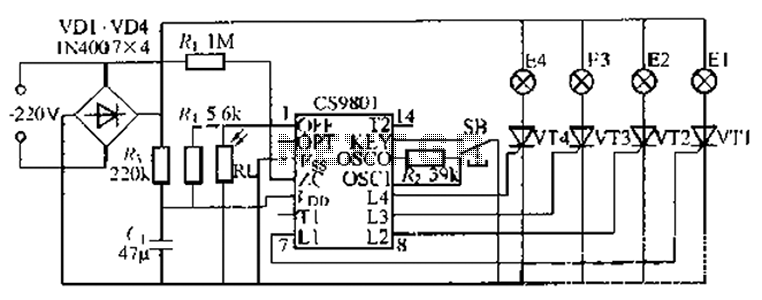
The ASIC is a flashing light string controller featuring four outputs. It includes a single key cycle control with six different lighting effects, and it allows for the selection of either 16 or 8 patterns. The circuit incorporates a...
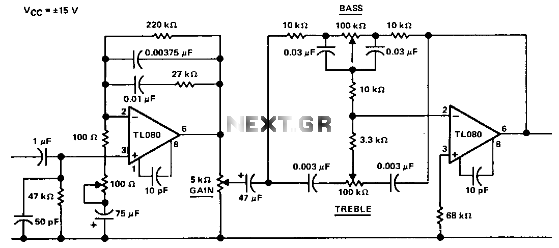
The circuit represents an "Americanized" version of the Baxandall negative-feedback tone control. At very low frequencies, the reactance of the capacitors is sufficiently high that they can be treated as open circuits, with the gain being regulated by the...
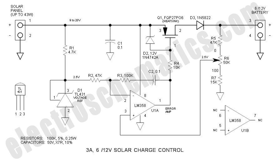
This solar charge controller integrates multiple features into a single design, including a 3A current rating, low dropout voltage (LDO), and a range of voltage adjustment capabilities. The solar charge controller is a critical component in solar energy systems, tasked...
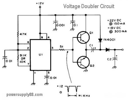
This circuit diagram represents a DC voltage doubler and DC converter. It is designed to convert a 12V DC power supply into outputs of 24V DC and 18V DC. Nearly any PNP or NPN power transistors can be utilized...