Amplifier Distortion
1. Definition of Amplifier Distortion
1.1 Definition of Amplifier Distortion
Amplifier distortion refers to undesirable changes in the output signal of an amplifier compared to its input signal. These changes can manifest in various forms, including the alteration of amplitude, frequency, phase, or waveform, leading to inaccuracies that may affect the performance of electronic systems. Understanding these distortions is crucial for engineers and researchers in designing high-fidelity audio systems, RF circuits, and precision measurement instruments.
A key aspect of amplifier distortion is its classification into different types: linear and nonlinear distortion. Linear distortion occurs when the amplifier output signal preserves the original waveform’s frequency characteristics but alters its amplitude. Conversely, nonlinear distortion arises from amplifiers exhibiting non-proportional amplification across varying signal levels, often introducing harmonic and intermodulation products that were not present in the input signal. This distinction is pivotal, as linear distortions typically manifest as frequency response issues, while nonlinear distortions yield additional unwanted frequencies that can corrupt the output signal.
Key Types of Distortion
- Harmonic Distortion: This type occurs when the output signal contains frequencies that are integer multiples of the input frequency. It is quantified by the Total Harmonic Distortion (THD) parameter, which indicates the percentage of the output signal that is harmonically distorted.
- Intermodulation Distortion (IMD): IMD arises when two or more signals interact, producing new frequencies not present in the original signals, usually at sums and differences of the input frequencies. This is critical in communications systems where channel fidelity is necessary.
- Crosstalk: This refers to unwanted interactions between multiple signal paths, wherein one signal affects another, leading to distortion. It is of particular concern in multi-channel systems.
Practical Implications
In real-world applications, the consequences of amplifier distortion can be profound. For instance, in audio amplifiers, excess harmonic and intermodulation distortion can lead to listener fatigue due to an undesired coloration of sound. In telecommunications, crosstalk and intermodulation can degrade signal integrity, resulting in increased error rates in data transmission. Consequently, understanding and minimizing amplifier distortion is vital for achieving high performance in electronic systems.
Evaluating distortion often involves employing analytical techniques and tools such as distortion analyzers and oscilloscopes, which allow engineers to visualize and quantify the performance of amplifiers under various operational conditions. Continuous innovation in amplifier design, including feedback circuits and digital signal processing (DSP), seeks to minimize these distortive effects and improve overall fidelity.
Where \(V_1\) is the amplitude of the fundamental frequency, and \(V_n\) are the amplitudes of the harmonic components. Such equations serve to quantify the effectiveness of methods designed to reduce distortion, guiding further advancements in amplifier technology.
1.2 Importance of Distortion Analysis
In the realm of amplifiers, distortion analysis plays a crucial role in assessing their performance and suitability for various applications. Understanding distortion is not just a theoretical endeavor; it holds significant practical implications that affect the quality and fidelity of audio, video, and communication systems.
Distortion refers to the alteration of the output signal of an amplifier compared to its intended or ideal response. It is essential to differentiate between the various types of distortion—harmonic distortion, intermodulation distortion, and digital distortion—as they impact the signal integrity in distinct ways.
Signal Integrity and Quality
The accuracy of the reproduced signal is a primary concern in applications such as audio amplification, where high-fidelity performance is desired. An amplifier that introduces excessive harmonic distortion will generate an output signal that deviates significantly from the original input waveform. This can lead to undesirable effects such as a "muddy" sound in audio applications or inaccurate color reproduction in video systems.
The Role of Feedback in Distortion
The implementation of feedback in amplifier design serves to mitigate distortion. By applying negative feedback, engineers can reduce both harmonic and intermodulation distortion. The principle behind this is that feedback compares the output with the input, and any deviation is corrected. However, the choice of feedback network also influences the amplifier's stability and bandwidth, creating a balance that must be carefully managed.
Mathematical Modeling of Distortion
To quantify distortion, it is important to employ the correct mathematical tools. For example, the total harmonic distortion (THD) can be calculated as follows:
where \(V_1\) is the amplitude of the fundamental frequency, and \(V_n\) represents the amplitudes of the harmonic components. Analyzing THD provides a quantitative means to evaluate amplifier performance and assists in design decisions.
Real-World Applications
In commercial audio equipment, for instance, specifications often include maximum allowable distortion levels to guide consumers in selecting equipment based on their quality requirements. For RF amplifiers used in communication systems, managing distortion is critical to maintain signal clarity and avoid interference.
In conclusion, distortion analysis is not simply a niche subject within the field of electronics; it is central to the development of effective and reliable amplifier systems. As technology progresses, understanding and managing distortion will remain vital for achieving enhanced performance across a range of applications.
1.3 Types of Distortion
Understanding Amplifier Distortion
Amplifier distortion refers to any alteration in an amplifier's output signal compared to its input signal, typically characterized by unwanted changes in the waveform. Comprehensive knowledge of the types of distortion is essential for advanced engineers, researchers, and physicists seeking to design high-fidelity audio systems, communication devices, and other electronics. This section delves into the various classifications of distortion, their origins, and implications in practical applications.1.3.1 Linear vs. Non-Linear Distortion
Distortion can primarily be categorized into two groups: linear and non-linear distortions. Linear distortion occurs when the output signal deviates from the input signal in a way that maintains the original waveform shape but alters its frequency response. For instance, phase distortion exemplified by a shift in phase relationships between frequency components can lead to significant alterations in audio quality, even when the amplitude remains affectively consistent. In contrast, non-linear distortion arises when the output signal's relationship with the input is not proportional. This introduces harmonic content that wasn’t present in the original signal, often resulting in a compressed or “squashed” sound. For example, an audio amplifier's clipping occurs when the output is driven beyond its maximum linear range, generating significant harmonic distortion that could be perceived as a "harsh" or unpleasant sound.1.3.2 Harmonic Distortion
Harmonic distortion, a specific subset of non-linear distortion, is defined by the introduction of harmonics, which are integral multiples of the original frequencies within a signal. This phenomenon can be quantitatively assessed using the Total Harmonic Distortion (THD) metric, formulated as:1.3.3 Intermodulation Distortion
While harmonic distortion incorporates multiple frequencies that share harmonic relationships, intermodulation distortion (IMD) is the result of two or more frequencies interacting to produce new frequencies that are combinations of the original signals. This can impair audio clarity by introducing unwanted artifacts. It is formulated as follows:1.3.4 Frequency Response Distortion
Moreover, distortion can emerge from frequency response issues where certain frequencies are unevenly amplified across the bandwidth. This could happen due to components within the amplifier failing to respond uniformly to varying frequencies, leading to detrimental impacts such as bass boost or roll-off effects impacting audio quality in real-world applications. In many applications, speaker design and amplifier selection must contend with this type of distortion. Recognizing the importance of both frequency response and distortion will influence design choices, particularly in home audio systems or professional sound reinforcement setups.1.3.5 Practical Relevance
Addressing amplifier distortion is essential in modern electronic design, especially in fields such as audio engineering, telecommunications, and instrumentation. Engineers often implement various compensation and feedback mechanisms to minimize distortive effects. Recognizing the different types of distortion allows them to design systems that achieve the best possible linearity and fidelity, regardless of changes in load conditions or signal characteristics. Understanding amplifier distortion can lead to better choices in system design, enhance performance evaluation techniques, and inspire innovation in methodologies to reduce unwanted effects systematically.2. Harmonic Distortion
2.1 Harmonic Distortion
Harmonic distortion is a crucial aspect of amplifier performance, often dictating the fidelity with which an amplifier can reproduce an input signal. Understanding this phenomenon requires a blend of theoretical knowledge and practical applications. To begin with, harmonic distortion occurs when an amplifier generates output signals that are not strictly proportional to the input signal, producing additional frequencies that are harmonics of the input frequency. This can introduce undesirable effects, such as a change in timbre, which is particularly noticeable in audio amplifiers.Understanding Harmonics
To delve into harmonic distortion, we first need to understand what harmonics are. In the context of signal processing, a harmonic is an integer multiple of a fundamental frequency. For example, if a signal contains a fundamental frequency \( f_0 \), its harmonics will be at frequencies \( 2f_0 \) (2nd harmonic), \( 3f_0 \) (3rd harmonic), and so forth. In mathematical terms, if we denote the input signal as: $$ x(t) = A \sin(2\pi f_0 t) $$ Where: - \( A \) is the amplitude, - \( f_0 \) is the fundamental frequency, - \( t \) is time. The output of the amplifier, in the presence of harmonic distortion, may be represented mathematically as: $$ y(t) = A \sin(2\pi f_0 t) + B \sin(2\pi 2f_0 t) + C \sin(2\pi 3f_0 t) + \cdots $$ Here, \( B \) and \( C \) are constants representing the amplitudes of the 2nd and 3rd harmonics, respectively.Types of Harmonic Distortion
Harmonic distortion can primarily be characterized into two types:- Odd-order Harmonics: Typically arise in unsymmetrical waveforms and are perceived as displeasing sounds. Common examples are third, fifth, and seventh harmonics.
- Even-order Harmonics: Generally have a more pleasant tonal quality but can still cause distortion if the output is not well managed. Examples include the second, fourth, and sixth harmonics.
Mathematical Representation of Total Harmonic Distortion (THD)
A key parameter used to quantify harmonic distortion is Total Harmonic Distortion (THD), defined as the ratio of the sum of the powers of all harmonic components to the power of the fundamental frequency. Mathematically, THD can be expressed as: $$ THD = \frac{\sqrt{P_2 + P_3 + P_4 + \cdots}}{P_1} $$ Where: - \( P_1 \) is the power of the fundamental frequency, - \( P_2, P_3, P_4, \dots \) represent the powers of the harmonic components. This equation allows engineers to assess the quality of an amplifier. A lower THD value typically indicates a cleaner, more faithful reproduction of the input signal.Real-World Application of Harmonic Distortion Analysis
In practice, various measurement techniques can be employed to ascertain the harmonic distortion levels in amplifiers. Instruments like spectrum analyzers provide visual graphs representing the output frequency spectrum, which can help in identifying the presence and amplitude of harmonic components. Furthermore, in high-fidelity audio systems, specific design approaches, such as feedback mechanisms, can be implemented to minimize distortion: - Negative Feedback: Applying feedback from the output back to the input reduces discrepancies between output and input, thereby minimizing distortion. - Class A versus Class B Amplifiers: The operational classes of amplifiers can also influence harmonic distortion characteristics. Class A amplifiers typically exhibit lower harmonic distortion than Class B due to their linear operation over a larger portion of the input signal cycle. In conclusion, harmonic distortion is a pivotal concept in understanding amplifier performance. Mastery of this topic not only aids in designing better amplifiers but also enhances the overall audio experience by ensuring high-fidelity playback of signals with minimum unwanted alterations.Intermodulation Distortion
Understanding Intermodulation Distortion
Intermodulation distortion (IMD) represents a critical concern in amplifier design, particularly in scenarios involving multi-tone signals. Unlike straightforward harmonic distortion, where individual frequencies are distorted, IMD emerges when two or more signals interact within a nonlinear system to produce additional unwanted frequencies. This effect particularly complicates the performance of amplifiers, and its implications extend into various real-world applications, such as telecommunications and audio processing. To illustrate IMD, imagine an amplifier receiving two sinusoidal inputs, with frequencies denoted as \(f_1\) and \(f_2\). In an ideal world, the output should only reflect these input frequencies. However, when the amplifier exhibits nonlinear characteristics, terms combining multiples of the input frequencies arise, introducing new frequencies at \(nf_1 \pm mf_2\) where \(n\) and \(m\) are integers. As a result, these additional components can interfere with the intended signals, compromising clarity and fidelity.The Mathematical Formulation
To develop a better understanding mathematically, consider the case where the input signals are expressed as: $$ x(t) = A_1 \sin(2\pi f_1 t) + A_2 \sin(2\pi f_2 t) $$ Where \(A_1\) and \(A_2\) denote the amplitudes of the respective frequencies. In practice, for a nonlinear amplifier, the output can be modeled as: $$ y(t) = k \cdot [A_1 \sin(2\pi f_1 t) + A_2 \sin(2\pi f_2 t)] + d(x(t)) $$ Here, \(d(x(t))\) signifies the deviation introduced by the nonlinearity, which leads to the generation of new frequency components. The common mathematical form of \(d\) in the context of a cubic nonlinearity may be expressed as: $$ d(x(t)) = B_2 x(t)^2 + C_3 x(t)^3 $$ Where \(B_2\) and \(C_3\) articulate the effects of the quadratic and cubic terms, respectively. After the expansion of this function, one discovers new frequency terms arising at \(f_1 + f_2\), \(f_1 - f_2\), \(2f_1\), and \(2f_2\), among others. The expansion leads us to identify dominant intermodulation products, particularly the third-order intermodulation distortion (IMD3), represented by: $$ IMD3 = 2f_1 - f_2 \quad \text{and} \quad 2f_2 - f_1 $$ This aspect of the harmonic generation illustrates the unwanted interaction that occurs within the amplifier, which translates into the distortion issues seen in many applications.Practical Implications of Intermodulation Distortion
In the realm of RF communications, a prominent application of understanding IMD lies in the design of transmitters and receivers, particularly for systems such as cellular networks. Nonlinearities in power amplifiers often result in significant interference, an issue exacerbated by the design constraints imposed by spectral efficiency. Moreover, audio signal processing conveys a similar need for precision. If an audio amplifier drives multiple frequencies simultaneously—such as during a musical performance—IMD can corrupt the desired sound output, introducing artifacts that detract from the listener's experience. As such, many high-quality audio amplifiers employ linearization techniques, aiming to minimize this distortion through careful engineering strategies. To conclude, intermodulation distortion is more than just an obscure mathematical concern; it incorporates indispensable elements of nonlinearity that affect various domains of technology. By grasping the nuances of IMD, engineers can bolster amplifier designs and achieve more reliable communication systems as well as enhanced auditory experiences.2.3 Phase Distortion
As we delve into the realm of amplifier distortion, phase distortion emerges as a distinct and significant issue that can impact audio fidelity and signal integrity. Unlike amplitude distortion, which alters the relative strength of various frequency components, phase distortion affects the timing relationships between these components. This has profound implications for the perception of sound and the overall functionality of electronic systems. Understanding phase distortion begins with the essential concept of phase itself. The phase of a signal refers to the position of a point within a waveform cycle at a given time. Mathematically, the phase of a continuous signal can be described as: $$ \phi(t) = \omega t + \phi_0 $$ where \( \omega \) is the angular frequency, \( t \) is time, and \( \phi_0 \) is the initial phase. Amplifiers can introduce phase shifts as they process signals, often due to frequency-dependent components within their circuit designs. For instance, in a linear amplifier, the transfer function can be derived from its frequency response. A simple first-order low-pass filter, which is often utilized in amplifiers, exhibits a phase shift that can be computed from its transfer function: $$ H(s) = \frac{1}{1 + s/\omega_c} $$ where \( s \) is the complex frequency variable and \( \omega_c \) is the cutoff frequency. The phase shift introduced by this filter can be expressed as: $$ \phi = -\tan^{-1}\left(\frac{\omega}{\omega_c}\right) $$ This relation shows that as the frequency approaches the cutoff \( \omega_c \), the phase shift increases, leading to a delay in the output signal relative to the input. To better understand the implications of phase distortion, we can consider a real-world scenario: when multiple frequency components are combined, such as in the case of musical signals, phase relationships contribute significantly to the perceived timbre and spatial localization of sound. When an amplifier causes differential phase delays among these components, it can lead to a muddied sound or an unnatural representation of the original audio. For example, when two tones are played simultaneously, if one tone is delayed in phase relative to the other, the resulting interference can create a phenomenon known as comb filtering. This results in peaks and notches in the frequency response, which can drastically alter the audible characteristics. Engineers often use phase compensation techniques to mitigate such effects, striving for a more consistent phase response across the frequency spectrum. In practical applications, phase distortion becomes particularly critical in high-fidelity audio systems, communication systems, and even in digital processing applications. Audio engineers and designers utilize advanced circuit designs, including feedback networks and all-pass filters, to control and correct phase shifts effectively. Such methods ensure that the audible signal retains its clarity and definition, achieving fidelity that aligns closer to the original sound. As we continue to explore amplifier distortion in the subsequent sections, it will be crucial to evaluate the methods for measuring and compensating for phase distortion in both analog and digital contexts. This understanding will not only enhance our design capabilities but also improve our ability to produce high-quality sound and signal processing systems.2.4 Signal Clipping
In the realm of amplifier distortion, signal clipping represents a critical phenomenon that can significantly affect audio fidelity and signal integrity. Understanding signal clipping is essential for engineers and researchers who grapple with amplification circuits across various applications, ranging from audio systems to RF amplifiers.
Defining Signal Clipping
Signal clipping occurs when an amplifier is driven beyond its maximum output capacity, resulting in a signal waveform that is "clipped" at the peaks and troughs. This non-linear distortion happens when the input signal exceeds the amplifier's voltage or current limits, and the output waveform is no longer a faithful representation of the input. The result is not just a simple truncation; it introduces new frequency components into the signal, which can drastically alter its spectral content.
The Mechanism of Signal Clipping
The mechanism behind signal clipping can be understood by analyzing the behavior of an ideal amplifier. An ideal amplifier states that the output voltage \( V_{out} \) should be proportional to the input voltage \( V_{in} \):
where \( A \) is the gain of the amplifier. However, every real amplifier has a maximum output voltage limit, denoted as \( V_{max} \). When the input signal exceeds the thresholds dictated by this limit, the output voltage cannot increase proportionally, and clipping occurs. Graphically, if one includes the maximum output level, the ideal linear relationship becomes a horizontal line at the clipping point, resembling a square wave form.
Mathematical Representation of Clipping
For practical analysis, let's define the output clipping behavior mathematically. When a sinusoidal voltage signal is applied:
where \( V_{m} \) is the maximum amplitude and \( f \) is the frequency. The output will only be valid until \( V_{m} \) exceeds \( V_{max}/A \). Hence, if we denote the output voltage as:
This segmented function defines the operation of the amplifier in the linear region and shows how it behaves under clamping, leading to distortion.
Effects of Clipping on Audio Signals
In audio systems, signal clipping is particularly detrimental. As the peaks of the audio waveform flatten, harmonic distortion is introduced. The resultant sound is often perceived as harsh or unpleasant. Furthermore, the introduction of high-frequency harmonics can cause intermodulation distortion, which can create additional overtones not present in the original sound.
For example, if a clean sine wave is clipped, the output may produce a square wave, leading to a spectrum rich in odd harmonics:
Where \( n \) are the odd harmonics \( 1, 3, 5, ... \). This equation reflects the fundamental frequency and the harmonics created in the output waveform due to clipping.
Practical Implications and Applications
In both consumer and professional audio equipment, managing signal clipping is crucial. Techniques such as dynamic range compression, limiting, and careful gain staging can help control the risk of clipping. Engineers must design amplifiers with appropriate headroom to mitigate distortion. Moreover, understanding the performance characteristics of different amplifier classes (A, B, AB, D) is vital, as each class reacts differently under conditions of overload.
Thus, the comprehension of signal clipping not only informs the design of amplifiers but also enhances the entire sound reproduction chain by ensuring clarity and fidelity in audio playback.
3. Non-Linearity in Amplifiers
3.1 Non-Linearity in Amplifiers
Amplifiers are essential components in electronic systems, playing a crucial role in processing signals. However, their primary function is often compromised by non-linearity, which can significantly affect the quality and fidelity of amplified signals. Non-linearity in amplifiers can introduce distortion, which results in a deviation from the original input signal waveforms. Understanding this phenomenon is vital for engineers and researchers in designing high-performance systems.
The inherent non-linearity in an amplifier can be traced back to various factors, including the characteristics of the active devices used, biasing conditions, and operational conditions such as temperature and frequency. These non-linear behaviors lead to several types of distortion, including harmonic distortion, intermodulation distortion, and amplitude distortion.
Understanding Non-Linearity
To quantitatively analyze non-linearity, consider a system where the output voltage \( V_{out} \) can be expressed as a Taylor series expansion around the input voltage \( V_{in} \):
In this expression, \( a_1 \) represents the linear term, while \( a_2 \) and \( a_3 \) correspond to the first and second order non-linear terms, respectively. The presence of these non-linear terms leads to a distortion of the signal. In practical applications, it is important to minimize the contribution of these non-linear terms to ensure high fidelity of the amplified signal.
Examples of Non-Linearity Induced Distortions
- Harmonic Distortion: This occurs when signals contain frequencies that are integer multiples of the original frequency. It can be measured using Total Harmonic Distortion (THD) which is defined as:
- Intermodulation Distortion: This arises when two or more signals are amplified simultaneously, causing additional unwanted frequencies that are the sum and difference of the original frequencies.
- Amplitude Distortion: This type of distortion occurs when the gain of the amplifier depends on the amplitude of the input signal, leading to a non-linear relationship between the input and output amplitudes.
These distortions can severely impact the performance of communication systems, audio devices, and many other applications where signal integrity is paramount. Engineers often employ various linearization techniques and feedback mechanisms to counteract the adverse effects of non-linearity, thereby enhancing the overall performance of amplifier circuits.
Real-World Applications
Understanding non-linearity in amplifiers not only helps in improving performance metrics like signal-to-noise ratio (SNR) and gain accuracy but also plays a significant role in developing high-fidelity audio equipment, RF transmitters, and high-speed communication devices. For instance, in audio amplifiers, minimizing harmonic distortion is crucial for delivering a clear and natural sound quality. Similarly, in RF amplifiers, controlling intermodulation distortion is essential for effective signal transmission without interference.
This understanding also affects design choices regarding component selection, biasing, and feedback mechanisms, highlighting how scientific principles translate into practical engineering applications.
3.2 Load Impedance Effects
In the landscape of amplifier distortion, the load impedance is a critical factor that significantly influences amplifier performance. Load impedance refers to the resistance that the output stage of an amplifier encounters, and understanding its implications is essential for optimizing amplifier design and minimizing distortion. This section explores the relationship between load impedance and amplifier distortion, considering how variations in impedance can affect linearity, gain stability, and overall sound quality.
Amplifiers are designed to deliver optimal performance under specified conditions, typically defined by an ideal load impedance. When the actual load impedance deviates from this ideal, several consequences arise, chiefly affecting the amplifier’s output characteristics.
Effects of Load Impedance on Linearity
Linearity refers to an amplifier's ability to produce an output signal that accurately reflects the input signal. When the load impedance is mismatched, specifically lower than expected, the amplifier may enter a state of nonlinearity. This nonlinearity manifests primarily through two forms of distortion: harmonic distortion and intermodulation distortion (IMD).
To quantify the effects of load impedance on linearity, we need to consider the small-signal model of the amplifier. Using a simplified representation of a typical voltage amplifier, the output voltage \( V_{out} \) can be expressed as:
where \( A_{v} \) is the voltage gain and \( V_{in} \) is the input voltage. As the load impedance, represented as \( R_L \), decreases, the total load current increases, placing additional stress on the amplifier's output stage. This, in turn, can lead to clipping, where the amplifier cannot reproduce the input signal accurately at higher levels, which contributes to significant harmonic distortion. The total harmonic distortion (THD) can be expressed as:
where \( V_1 \) is the fundamental frequency component, and \( V_n \) represents the harmonics. As the load impedance decreases, THD increases, highlighting the importance of maintaining an appropriate impedance match.
Gain Stability and Load Impedance
Amp gain is another aspect highly sensitive to load impedance. Ideally, the gain of an amplifier should remain constant, irrespective of the load. However, in practical terms, the gain is affected by load variations. Amplifiers with feedback mechanisms are particularly chose for their ability to maintain stable gain across a range of load conditions.
Let’s consider a feedback amplifier where the gain with feedback \( A_{fb} \) can be expressed as:
Here, \( A_{0} \) is the open-loop gain and \( \beta \) is the feedback factor. As the load impedance decreases, the effective \( \beta \) can change, often leading to reduced gain stability. This instability creates unwanted artifacts and further distorts the output signal, deviating from the original input waveform.
Real-World Applications
In professional audio systems, the load impedance plays a pivotal role in sound quality and performance. For instance, when designing an audio amplifier for concert applications, achieving a proper load impedance (usually 4 to 8 ohms for speakers) is crucial to prevent distortion during high volume outputs. Improper impedance matching in such scenarios could lead to significant performance degradation, affecting not just audio fidelity but also the longevity of the equipment.
Furthermore, in telecommunications, the load impedance is vital for optimizing signal integrity across long distances. Impedance matching techniques, such as using transformers or specific circuit designs, are employed to minimize reflections and transmission losses that can arise from impedance mismatches.
Understanding the effects of load impedance is essential for engineers tasked with designing reliable and efficient amplifiers. By ensuring an appropriate load is presented to an amplifier, not only can distortion be minimized, but also the performance of the overall system can be maximized, leading to high-fidelity outputs.
Conclusion
In summary, the load impedance has a profound effect on amplifier performance, specifically influencing linearity, gain stability, and susceptibility to distortion. Recognizing these principles will allow engineers to design better amplifiers and provide higher quality outputs in practical applications.
3.3 Power Supply Variations
Power supply variations represent a critical aspect of amplifier distortion, often overlooked yet fundamental in advanced electronic circuit design. The performance of an amplifier is intricately linked to the characteristics of its power supply—the source that provides the necessary voltage and current. Understanding how variability in the power supply affects amplifier performance is essential for achieving high fidelity audio and preventing unwanted signal degradation.
Variations in power supply can arise from several sources, including fluctuations in mains voltage, transient load conditions, and the inherent properties of the power supply circuit itself. Each of these factors can introduce non-linearity and, consequently, distortion in the amplifier's output signal.
Fluctuations due to Mains Voltage
The primary source of power supply variation stems from the fluctuation in mains voltage. In many regions, the standard a.c. mains supply is not constant—often varying due to load demands across the grid. Such fluctuations can directly affect the operating point of the amplifier’s transistors, potentially leading to distortion. The variations manifest as amplitude modulation of the output signal, where the peaks and troughs of the input signal are altered unexpectedly.
Mathematically, this can be expressed through the voltage gain (A) of an amplifier as:
Where R_f is the feedback resistance and R_{in} is the input resistance. A change in supply voltage alters V_{out} relative to V_{in}, thereby skewing the gain and introducing distortion. For example, if V_{supply} dips, the gain reduces, leading to clipping of the output when the input signal rises beyond a certain threshold. Thus, maintaining a stable power supply is crucial.
Transient Load Conditions
Transient conditions, such as sudden changes in the load connected to the amplifier, can induce a voltage drop in the power supply. This phenomenon is particularly pronounced in Class A amplifiers, where the output stage is always conducting and can respond poorly to rapid changes in current demand. This variability can lead to intermodulation distortion, which occurs when two or more signals are present and interact in a non-linear fashion.
To study this mathematically, consider the power delivered to a load (R_L) can be defined as:
As the load abruptly changes, the voltage (V) across the load can diminish due to inadequate current supply from the power supply, inadvertently distorting the original input signal ratio.
Power Supply Circuit Characteristics
The inherent characteristics of the power supply circuitry also contribute to distortion. For instance, power supplies can have ripple voltage from rectification or inadequate filtering, which can introduce unwanted noise and frequency components into the power rail. This noise translates through the amplifier, manifesting as an audible distortion effect.
To analyze this mathematically, we note that the ripple voltage can be quantified as:
Where V_{dc} is the average output voltage, while V_{peak} refers to the peak voltage of the rectified supply. Throughout amplification, this ripple will effectively modulate the output and shift frequency components, pushing the amplified signal outside of its intended frequency band.
Conclusion
In conclusion, variations in power supply pose significant challenges to amplifier fidelity, resulting in various types of distortion, including amplitude modulation and intermodulation effects. Understanding the mechanisms by which power supply fluctuations affect amplifier operation is vital for engineers and researchers striving for optimal performance and minimal distortion in advanced audio and electronic systems. Counteracting these variations often involves employing voltage regulation techniques, sufficient filtering, and waste of energy management strategies to stabilize the power supply.
4. Equipment for Distortion Measurement
4.1 Equipment for Distortion Measurement
In the realm of amplifier distortion analysis, precise measurement is paramount. Understanding the fundamental and harmonic distortions that can arise in signal processing circuits involves not only theoretical knowledge but also the right tools. The measurement equipment used must be capable of accurately capturing and analyzing the minute variations in amplitude and phase that signify distortion.Essential Measurement Devices
To effectively measure amplifier distortion, the following equipment is essential:- Oscilloscope: This is a critical tool used to visualize voltage signals over time. Modern digital oscilloscopes come equipped with high sampling rates and bandwidth that enable clear observation of distorted waveforms. Capturing the waveform allows engineers to compare the output signal directly against the input, helping in identifying any deviations that lead to distortion.
- Frequency Analyzers: Analyzers such as spectrum analyzers or FFT (Fast Fourier Transform) analyzers can be employed to see the spectral components of the output signal. These tools are invaluable for identifying harmonic distortions by showing content at frequencies that are integer multiples of the fundamental frequency.
- Signal Generators: These devices produce varying waveforms (sine, square, triangle, or arbitrary) that are fed into the amplifier for testing. Choosing the right frequency and amplitude is essential since these parameters heavily influence the distortion characteristics observed in the amplifier's output.
- Distortion Analyzers: Specifically designed for measuring the total harmonic distortion (THD) or intermodulation distortion (IMD), these analyzers can provide direct percentages of distortion, making them a focal point for quality testing in audio and RF applications.
Signal Path and Setup
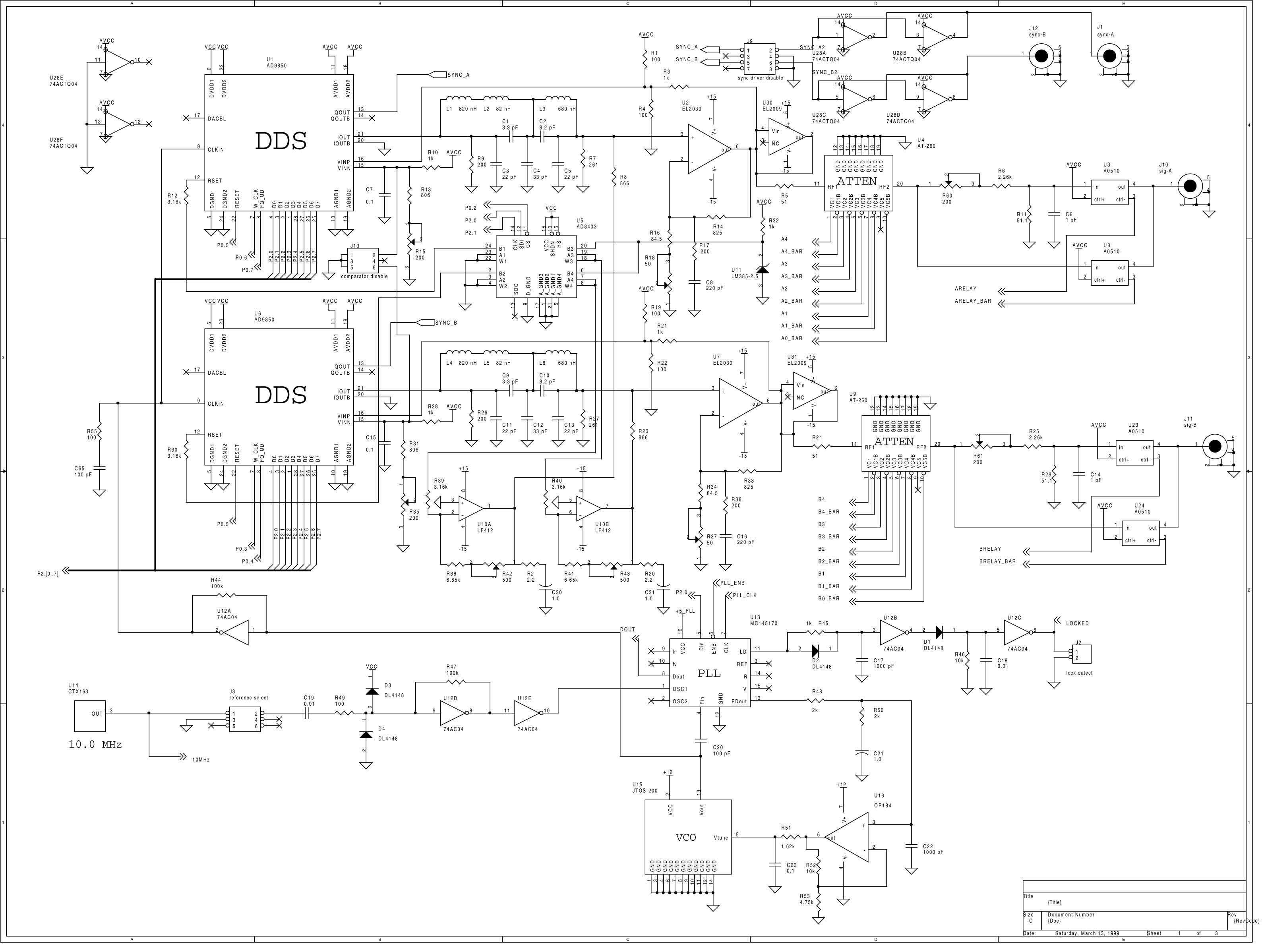
The organization of measurement equipment in the signal path is critical to obtaining accurate results. Typical measurement setups include: 1. A signal generator producing a test waveform directly feeds the amplifier under test. 2. The output of the amplifier is connected to both the oscilloscope and the distortion analyzer, allowing simultaneous monitoring and assessment. 3. The oscilloscope provides a time-domain view of the output signal, while the distortion analyzer can provide frequency-domain analysis. Ensuring that all devices are calibrated and synchronized is crucial for reliable measurements. A sample diagram illustrating a basic measurement setup could show the connections between these pieces of equipment, helping readers visually recognize the configuration.Practical Applications of Distortion Measurement
Understanding amplifier distortion through precise measurements has profound implications. For instance, in audio engineering, ensuring low distortion levels is crucial for high-fidelity sound reproduction. In RF applications, excessive distortion can lead to degradation of signal quality and communication errors. Additionally, in power electronics, distortion can affect the efficiency of power conversion operations, impacting overall system performance. Therefore, the proper measurement equipment not only aids in detecting issues but also contributes to the design and refinement of amplifiers, ensuring they meet high-performance standards across diverse applications.4.1 Equipment for Distortion Measurement
In the realm of amplifier distortion analysis, precise measurement is paramount. Understanding the fundamental and harmonic distortions that can arise in signal processing circuits involves not only theoretical knowledge but also the right tools. The measurement equipment used must be capable of accurately capturing and analyzing the minute variations in amplitude and phase that signify distortion.Essential Measurement Devices
To effectively measure amplifier distortion, the following equipment is essential:- Oscilloscope: This is a critical tool used to visualize voltage signals over time. Modern digital oscilloscopes come equipped with high sampling rates and bandwidth that enable clear observation of distorted waveforms. Capturing the waveform allows engineers to compare the output signal directly against the input, helping in identifying any deviations that lead to distortion.
- Frequency Analyzers: Analyzers such as spectrum analyzers or FFT (Fast Fourier Transform) analyzers can be employed to see the spectral components of the output signal. These tools are invaluable for identifying harmonic distortions by showing content at frequencies that are integer multiples of the fundamental frequency.
- Signal Generators: These devices produce varying waveforms (sine, square, triangle, or arbitrary) that are fed into the amplifier for testing. Choosing the right frequency and amplitude is essential since these parameters heavily influence the distortion characteristics observed in the amplifier's output.
- Distortion Analyzers: Specifically designed for measuring the total harmonic distortion (THD) or intermodulation distortion (IMD), these analyzers can provide direct percentages of distortion, making them a focal point for quality testing in audio and RF applications.
Signal Path and Setup
The organization of measurement equipment in the signal path is critical to obtaining accurate results. Typical measurement setups include: 1. A signal generator producing a test waveform directly feeds the amplifier under test. 2. The output of the amplifier is connected to both the oscilloscope and the distortion analyzer, allowing simultaneous monitoring and assessment. 3. The oscilloscope provides a time-domain view of the output signal, while the distortion analyzer can provide frequency-domain analysis. Ensuring that all devices are calibrated and synchronized is crucial for reliable measurements. A sample diagram illustrating a basic measurement setup could show the connections between these pieces of equipment, helping readers visually recognize the configuration.Practical Applications of Distortion Measurement
Understanding amplifier distortion through precise measurements has profound implications. For instance, in audio engineering, ensuring low distortion levels is crucial for high-fidelity sound reproduction. In RF applications, excessive distortion can lead to degradation of signal quality and communication errors. Additionally, in power electronics, distortion can affect the efficiency of power conversion operations, impacting overall system performance. Therefore, the proper measurement equipment not only aids in detecting issues but also contributes to the design and refinement of amplifiers, ensuring they meet high-performance standards across diverse applications.4.2 Common Measurement Techniques
The assessment of amplifier distortion requires precise measurement techniques that can accurately capture the minute imperfections impacting signal fidelity. Engineers and researchers utilize various methods to evaluate distortion across different types of amplifiers—be it linear or nonlinear, analog or digital. This section delves into the predominant measurement techniques employed in the field.
Understanding Distortion Measurement
Distortion in amplifiers can manifest in various forms, such as harmonic distortion, intermodulation distortion, and crossover distortion. The choice of measurement technique often depends on the type of distortion being analyzed. As we explore these techniques, we'll also touch upon their application in both laboratory settings and practical environments.
1. Harmonic Distortion Measurement
One of the most prevalent methods for measuring harmonic distortion is through the use of a Distortion Analyzer. This device typically employs a sine wave signal, which is fed into the amplifier. The output is then analyzed to determine the harmonic components using a spectrum analyzer. This method provides insights into the Total Harmonic Distortion (THD) level of the amplifier.
In mathematical terms, Total Harmonic Distortion is defined as:
Where \( V_1 \) is the fundamental frequency voltage, and \( V_n \) represents the nth harmonic voltage. This measurement allows for a quantitative assessment of amplifier performance and identifies the nonlinearities that may degrade audio quality in consumer electronics.
2. Intermodulation Distortion Measurement
Intermodulation distortion occurs when two or more signals mix within an amplifier, producing additional unwanted frequencies. To measure this type of distortion, a systematic approach is essential. A typical procedure involves:
- Injecting two tones (frequencies) into the amplifier.
- Using a spectrum analyzer to capture and analyze the output signal.
- Identifying the unwanted intermodulation products that fall outside the desired frequency range.
The efficiency of this technique lies in its ability to reveal the nonlinearity of the amplifier's response more accurately than simple harmonic distortion measurements. Accurate quantification of these products aids in understanding how an amplifier behaves under actual working conditions, particularly in RF applications.
3. Measuring Crossover Distortion
Crossover distortion typically appears in class B or class AB amplifiers, characterized by a failure to smoothly transition between the positive and negative halves of the input signal. To measure crossover distortion, a dual-tone signal generator can be used. This generator feeds a low-frequency signal to the amplifier while monitoring the output waveform.
Graphically, the output waveform is analyzed for flat regions or non-ideal transitions near zero crossings, which represent distortion. The visual observation can be quantified using oscilloscopes and is particularly useful in audio amplifier design, where sonic fidelity is critical.
4. Digital Techniques and Software Analysis
With advancements in technology, digital signal processing (DSP) has emerged as a valuable tool in distortion measurement. Software such as MATLAB or LabVIEW can analyze waveform data captured via high-resolution ADCs (Analog-to-Digital Converters).
These systems not only evaluate THD or IMD but also allow for custom algorithms that can simulate various real-world scenarios. For example, applying a Fourier Transform to the time-domain signal can yield a frequency spectrum, enabling detailed analysis of distortion characteristics across multiple frequencies.
Emphasizing the relevance, measuring techniques have a profound impact on the design and refinement of amplifiers used in audio engineering, telecommunications, and broadcasting. Accurate distortion assessments ensure that devices meet industry standards and consumer expectations.
In conclusion, understanding the common measurement techniques for amplifier distortion is essential for professionals striving to enhance signal integrity in diverse applications. These measurement approaches, whether traditional or digital, provide the analytical basis for improving amplifier design and advancing electronic systems.
4.2 Common Measurement Techniques
The assessment of amplifier distortion requires precise measurement techniques that can accurately capture the minute imperfections impacting signal fidelity. Engineers and researchers utilize various methods to evaluate distortion across different types of amplifiers—be it linear or nonlinear, analog or digital. This section delves into the predominant measurement techniques employed in the field.
Understanding Distortion Measurement
Distortion in amplifiers can manifest in various forms, such as harmonic distortion, intermodulation distortion, and crossover distortion. The choice of measurement technique often depends on the type of distortion being analyzed. As we explore these techniques, we'll also touch upon their application in both laboratory settings and practical environments.
1. Harmonic Distortion Measurement
One of the most prevalent methods for measuring harmonic distortion is through the use of a Distortion Analyzer. This device typically employs a sine wave signal, which is fed into the amplifier. The output is then analyzed to determine the harmonic components using a spectrum analyzer. This method provides insights into the Total Harmonic Distortion (THD) level of the amplifier.
In mathematical terms, Total Harmonic Distortion is defined as:
Where \( V_1 \) is the fundamental frequency voltage, and \( V_n \) represents the nth harmonic voltage. This measurement allows for a quantitative assessment of amplifier performance and identifies the nonlinearities that may degrade audio quality in consumer electronics.
2. Intermodulation Distortion Measurement
Intermodulation distortion occurs when two or more signals mix within an amplifier, producing additional unwanted frequencies. To measure this type of distortion, a systematic approach is essential. A typical procedure involves:
- Injecting two tones (frequencies) into the amplifier.
- Using a spectrum analyzer to capture and analyze the output signal.
- Identifying the unwanted intermodulation products that fall outside the desired frequency range.
The efficiency of this technique lies in its ability to reveal the nonlinearity of the amplifier's response more accurately than simple harmonic distortion measurements. Accurate quantification of these products aids in understanding how an amplifier behaves under actual working conditions, particularly in RF applications.
3. Measuring Crossover Distortion
Crossover distortion typically appears in class B or class AB amplifiers, characterized by a failure to smoothly transition between the positive and negative halves of the input signal. To measure crossover distortion, a dual-tone signal generator can be used. This generator feeds a low-frequency signal to the amplifier while monitoring the output waveform.
Graphically, the output waveform is analyzed for flat regions or non-ideal transitions near zero crossings, which represent distortion. The visual observation can be quantified using oscilloscopes and is particularly useful in audio amplifier design, where sonic fidelity is critical.
4. Digital Techniques and Software Analysis
With advancements in technology, digital signal processing (DSP) has emerged as a valuable tool in distortion measurement. Software such as MATLAB or LabVIEW can analyze waveform data captured via high-resolution ADCs (Analog-to-Digital Converters).
These systems not only evaluate THD or IMD but also allow for custom algorithms that can simulate various real-world scenarios. For example, applying a Fourier Transform to the time-domain signal can yield a frequency spectrum, enabling detailed analysis of distortion characteristics across multiple frequencies.
Emphasizing the relevance, measuring techniques have a profound impact on the design and refinement of amplifiers used in audio engineering, telecommunications, and broadcasting. Accurate distortion assessments ensure that devices meet industry standards and consumer expectations.
In conclusion, understanding the common measurement techniques for amplifier distortion is essential for professionals striving to enhance signal integrity in diverse applications. These measurement approaches, whether traditional or digital, provide the analytical basis for improving amplifier design and advancing electronic systems.
4.3 Interpreting Distortion Measurements
Understanding distortion measurements in amplifiers is essential for both the design of audio equipment and the broader field of signal processing. Distortion introduces unwanted artifacts in reproduced signals, which can significantly affect performance across various applications, from audio amplification to communications systems.
Distortion is generally quantified using a variety of metrics, each capturing different aspects of signal fidelity. Two of the most commonly used measures are Total Harmonic Distortion (THD) and Intermodulation Distortion (IMD). These metrics provide insights into how well an amplifier reproduces both single-frequency and multi-frequency signals, respectively.
Total Harmonic Distortion (THD)
THD is a vital parameter for evaluating the linearity of an amplifier's response. It quantifies the ratio of the sum of the powers of all harmonic components to the power of the fundamental frequency. Mathematically, THD can be expressed as:
Here, \( P_1 \) represents the power of the fundamental frequency, while \( P_2, P_3, \) through \( P_n \) correspond to the powers of the higher-order harmonics. The lower the THD value, the better the amplifier's performance in preserving the fidelity of the input signal.
Practical Relevance of THD
In audio systems, a THD of less than 0.1% is generally considered acceptable for most applications. However, high-fidelity audio systems aim for even lower values to prevent listener fatigue and ensure clarity. The importance of THD manifests in various real-world scenarios, such as in the design of guitar amplifiers, where harmonic richness is desired but excessive distortion is undesirable.
Intermodulation Distortion (IMD)
IMD arises when two or more signals interfere within a non-linear system, leading to additional frequencies that were not present in the original input. IMD is particularly important in communication systems where multiple signals coexist. It can be calculated similarly to THD:
In the equation above, \( P_1 \) and \( P_2 \) represent the powers of the individual input tones. IMD helps to assess how well an amplifier can manage signals without allowing cross-talk between different channels, which is crucial in multi-channel audio systems and RF applications where signal isolation is critical.
Case Studies and Historical Context
Historically, the interaction between THD and IMD has governed the growth of amplifier technologies. Early audiophiles favored tube amplifiers due to their warm harmonic distortion, while solid-state amplifiers became favored for their lower distortion levels and higher power outputs. Understanding and measuring distortion has led to advancements in feedback techniques, which can effectively mitigate these distortions in modern amplifiers.
By studying and accurately interpreting distortion measurements, engineers can design amplifiers tailored to specific applications, ensuring optimal performance and user satisfaction.
5. Design Strategies for Low Distortion
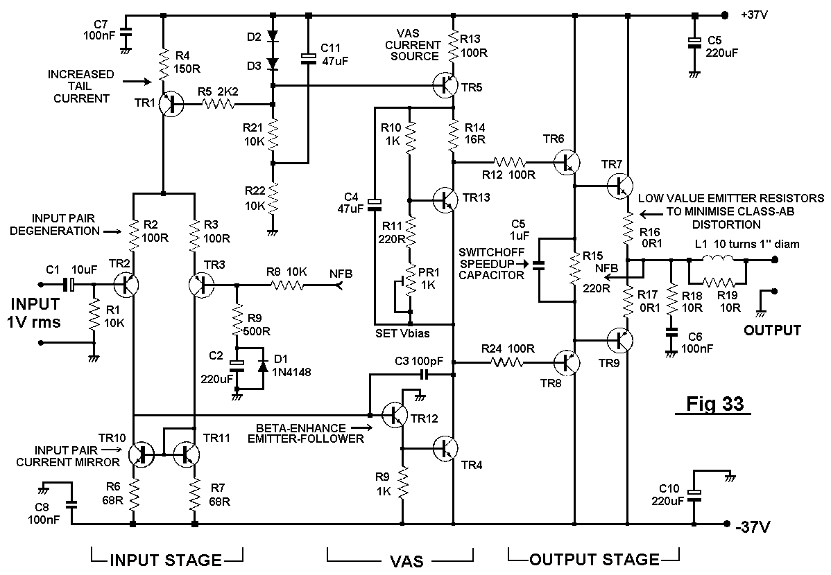
5.1 Design Strategies for Low Distortion
To achieve low distortion in amplifier circuits, it becomes vital to employ specific design strategies that cater to various types of distortions, including harmonic distortion, intermodulation distortion, and phase distortion. Each of these distortions can compromise the efficacy of amplifiers in both audio and RF applications. Understanding how to minimize such distortions ensures that the signals maintain fidelity through the amplification process.Understanding Distortions in Amplifiers
Before discussing strategies, it’s important to recognize what distortion means in a signal processing context. Distortion refers to any alteration in the original form of the signal, which can be categorized into several types:- Harmonic Distortion: This occurs when nonlinearities in the amplifier introduce harmonic frequencies that were not present in the original signal.
- Intermodulation Distortion: This arises when two or more signals mix, generating new frequencies that are harmonic combinations of the original signals.
- Phase Distortion: This is noticeable in systems where signal phase shifts occur, leading to time-domain distortion.
Utilizing Negative Feedback
One of the most effective methods for reducing distortion in amplifier circuits is through the use of negative feedback. This mechanism involves feeding a portion of the output signal back to the input in opposition to the input signal. The outcome is a reduction in gain but also a significant decrease in distortion. Mathematically, the gain with negative feedback, \( A_f \), can be derived from:Choosing the Right Topology
Selecting the appropriate amplifier topology plays a critical role in minimizing distortion. Different configurations affect distortion in various ways:- Class A Amplifiers: Known for their excellent linearity but with lower efficiency, Class A amplifiers are often preferred for applications where low harmonic distortion is paramount.
- Class B and Class AB Amplifiers: These designs offer better efficiency than Class A but can introduce crossover distortion at low signal levels, which needs to be compensated with design tweaks.
- Feedback Amplifiers: Designs that inherently incorporate feedback mechanisms can further help in managing various distortion types effectively.
Careful Component Selection and Matching
Another significant aspect of amplifier design for low distortion involves the careful selection and matching of components. Variations in transistor characteristics can significantly influence the distortion levels of amplifier circuits. Therefore, using tightly matched pairs of transistors in differential stages can help minimize variations that lead to increased distortion. Additionally, the choice of resistors and capacitors also impacts noise and distortion. Low-noise components, particularly in the input stage, further aid in reducing the distortion-levels through enhanced signal integrity.Implementation of Proper Power Supply Decoupling
To ensure consistent amplitude and signal quality, power supply decoupling is crucial. Instabilities in the power supply can result in modulation of the amplifier output, effectively introducing distortion. Bypass capacitors placed close to the power pins of the amplifier can reduce high-frequency noise, thereby enhancing overall performance. As a best practice, low-ESR (Equivalent Series Resistance) capacitors should be employed to minimize power supply ripple, ensuring the amplifier remains stable even under dynamic load conditions.Conclusion and Practical Implications
In applying these strategies, engineers can craft amplifiers that not only deliver high fidelity and low distortion but also meet the demands of various practical applications. From high-end audio equipment to telecommunications, the implications of low distortion are far-reaching, culminating in clearer, more accurate signal reproduction. As technology continues to evolve, the continuous innovation in amplifier design strategies remains paramount, allowing for ever-greater fidelity in sound and signal processing.5.1 Design Strategies for Low Distortion
To achieve low distortion in amplifier circuits, it becomes vital to employ specific design strategies that cater to various types of distortions, including harmonic distortion, intermodulation distortion, and phase distortion. Each of these distortions can compromise the efficacy of amplifiers in both audio and RF applications. Understanding how to minimize such distortions ensures that the signals maintain fidelity through the amplification process.Understanding Distortions in Amplifiers
Before discussing strategies, it’s important to recognize what distortion means in a signal processing context. Distortion refers to any alteration in the original form of the signal, which can be categorized into several types:- Harmonic Distortion: This occurs when nonlinearities in the amplifier introduce harmonic frequencies that were not present in the original signal.
- Intermodulation Distortion: This arises when two or more signals mix, generating new frequencies that are harmonic combinations of the original signals.
- Phase Distortion: This is noticeable in systems where signal phase shifts occur, leading to time-domain distortion.
Utilizing Negative Feedback
One of the most effective methods for reducing distortion in amplifier circuits is through the use of negative feedback. This mechanism involves feeding a portion of the output signal back to the input in opposition to the input signal. The outcome is a reduction in gain but also a significant decrease in distortion. Mathematically, the gain with negative feedback, \( A_f \), can be derived from:Choosing the Right Topology
Selecting the appropriate amplifier topology plays a critical role in minimizing distortion. Different configurations affect distortion in various ways:- Class A Amplifiers: Known for their excellent linearity but with lower efficiency, Class A amplifiers are often preferred for applications where low harmonic distortion is paramount.
- Class B and Class AB Amplifiers: These designs offer better efficiency than Class A but can introduce crossover distortion at low signal levels, which needs to be compensated with design tweaks.
- Feedback Amplifiers: Designs that inherently incorporate feedback mechanisms can further help in managing various distortion types effectively.
Careful Component Selection and Matching
Another significant aspect of amplifier design for low distortion involves the careful selection and matching of components. Variations in transistor characteristics can significantly influence the distortion levels of amplifier circuits. Therefore, using tightly matched pairs of transistors in differential stages can help minimize variations that lead to increased distortion. Additionally, the choice of resistors and capacitors also impacts noise and distortion. Low-noise components, particularly in the input stage, further aid in reducing the distortion-levels through enhanced signal integrity.Implementation of Proper Power Supply Decoupling
To ensure consistent amplitude and signal quality, power supply decoupling is crucial. Instabilities in the power supply can result in modulation of the amplifier output, effectively introducing distortion. Bypass capacitors placed close to the power pins of the amplifier can reduce high-frequency noise, thereby enhancing overall performance. As a best practice, low-ESR (Equivalent Series Resistance) capacitors should be employed to minimize power supply ripple, ensuring the amplifier remains stable even under dynamic load conditions.Conclusion and Practical Implications
In applying these strategies, engineers can craft amplifiers that not only deliver high fidelity and low distortion but also meet the demands of various practical applications. From high-end audio equipment to telecommunications, the implications of low distortion are far-reaching, culminating in clearer, more accurate signal reproduction. As technology continues to evolve, the continuous innovation in amplifier design strategies remains paramount, allowing for ever-greater fidelity in sound and signal processing.5.2 Feedback Techniques
The concept of feedback techniques in amplifiers is crucial in managing and minimizing amplifier distortion, thereby enhancing linearity and stability. Feedback refers to the practice of routing part of the output signal back to the input. The primary goal of implementing feedback is to improve the amplifier's performance metrics by counteracting unwanted characteristics, including distortion. When a feedback loop is introduced in an amplifier, it essentially alters the circuit's parameters. Depending on the nature of the feedback, we can divide it into two main categories—negative feedback and positive feedback.Negative Feedback
Negative feedback is widely employed in amplifier circuits to reduce distortion, improve bandwidth, and enhance overall stability. In this configuration, a portion of the output signal is fed back to the inverting input terminal of the amplifier. The key advantage of negative feedback is that it subtracts from the input signal, effectively compensating for any output fluctuations caused by distortion. When applying negative feedback, one can observe that the amplifier’s transfer function becomes less dependent on the non-linear characteristics of the active device (e.g., transistors, op-amps). Instead, it becomes more reliant on the linear components of the feedback path, thus allowing for increased linearity in the output signal. This is mathematically represented as follows: Consider an amplifier with a voltage gain \( A \) and a feedback factor \( \beta \). The overall voltage gain \( A_f \) with negative feedback can be expressed as: $$ A_f = \frac{A}{1 + A\beta} $$ Here, \( A \) represents the open-loop gain of the amplifier, and \( \beta \) represents the feedback ratio. This equation indicates that as the feedback fraction \( \beta \) increases (i.e., more feedback is applied), the overall gain \( A_f \) decreases but with improved characteristics like reduced distortion. Furthermore, negative feedback techniques can lead to a remarkable improvement in the linearity of the amplifier, crucial for high-fidelity applications such as audio amplification and signal processing. Incorporating reasonably high levels of feedback can significantly reduce harmonic distortion, measured as Total Harmonic Distortion (THD), which is pivotal in ensuring clear signal reproduction.Positive Feedback
In contrast, positive feedback can increase gain but may also introduce unwanted instability or oscillation. Here, part of the output is fed back to the non-inverting input terminal. While this feedback can amplify an input signal and enhance certain characteristics, it can also exacerbate distortion. Positive feedback can be useful in specific applications, such as oscillators where a desired frequency output is generated, but care must be taken to manage distortion and ensure stability.Applications of Feedback in Amplifiers
Feedback techniques are applied in various amplifier designs, including operational amplifiers, audio amplifiers, and RF amplifiers. Below are a few practical applications:- Operational Amplifiers: Negative feedback is crucial in operational amplifier circuits to create stable integrators, differentiators, and filters with minimal distortion.
- Audio Amplifiers: In high-fidelity audio systems, negative feedback effectively reduces distortion while maintaining a natural sound texture, crucial for enhancing listener experience.
- Instrumentation Amplifiers: These amplifiers utilize feedback to achieve high input impedance and gain stability, ensuring accuracy in sensor signal amplification.
- RF Amplifiers: Feedback in RF amplifiers can help suppress unwanted oscillations while maintaining desired gain, improving overall circuit reliability.
5.2 Feedback Techniques
The concept of feedback techniques in amplifiers is crucial in managing and minimizing amplifier distortion, thereby enhancing linearity and stability. Feedback refers to the practice of routing part of the output signal back to the input. The primary goal of implementing feedback is to improve the amplifier's performance metrics by counteracting unwanted characteristics, including distortion. When a feedback loop is introduced in an amplifier, it essentially alters the circuit's parameters. Depending on the nature of the feedback, we can divide it into two main categories—negative feedback and positive feedback.Negative Feedback
Negative feedback is widely employed in amplifier circuits to reduce distortion, improve bandwidth, and enhance overall stability. In this configuration, a portion of the output signal is fed back to the inverting input terminal of the amplifier. The key advantage of negative feedback is that it subtracts from the input signal, effectively compensating for any output fluctuations caused by distortion. When applying negative feedback, one can observe that the amplifier’s transfer function becomes less dependent on the non-linear characteristics of the active device (e.g., transistors, op-amps). Instead, it becomes more reliant on the linear components of the feedback path, thus allowing for increased linearity in the output signal. This is mathematically represented as follows: Consider an amplifier with a voltage gain \( A \) and a feedback factor \( \beta \). The overall voltage gain \( A_f \) with negative feedback can be expressed as: $$ A_f = \frac{A}{1 + A\beta} $$ Here, \( A \) represents the open-loop gain of the amplifier, and \( \beta \) represents the feedback ratio. This equation indicates that as the feedback fraction \( \beta \) increases (i.e., more feedback is applied), the overall gain \( A_f \) decreases but with improved characteristics like reduced distortion. Furthermore, negative feedback techniques can lead to a remarkable improvement in the linearity of the amplifier, crucial for high-fidelity applications such as audio amplification and signal processing. Incorporating reasonably high levels of feedback can significantly reduce harmonic distortion, measured as Total Harmonic Distortion (THD), which is pivotal in ensuring clear signal reproduction.Positive Feedback
In contrast, positive feedback can increase gain but may also introduce unwanted instability or oscillation. Here, part of the output is fed back to the non-inverting input terminal. While this feedback can amplify an input signal and enhance certain characteristics, it can also exacerbate distortion. Positive feedback can be useful in specific applications, such as oscillators where a desired frequency output is generated, but care must be taken to manage distortion and ensure stability.Applications of Feedback in Amplifiers
Feedback techniques are applied in various amplifier designs, including operational amplifiers, audio amplifiers, and RF amplifiers. Below are a few practical applications:- Operational Amplifiers: Negative feedback is crucial in operational amplifier circuits to create stable integrators, differentiators, and filters with minimal distortion.
- Audio Amplifiers: In high-fidelity audio systems, negative feedback effectively reduces distortion while maintaining a natural sound texture, crucial for enhancing listener experience.
- Instrumentation Amplifiers: These amplifiers utilize feedback to achieve high input impedance and gain stability, ensuring accuracy in sensor signal amplification.
- RF Amplifiers: Feedback in RF amplifiers can help suppress unwanted oscillations while maintaining desired gain, improving overall circuit reliability.
5.3 Choosing the Right Components
When designing amplifiers, particularly when focusing on reducing distortion, the selection of the right components is paramount. Each component influences the linearity and performance of the amplifier, and understanding their characteristics helps in making informed decisions to mitigate distortion. In this section, we will explore the critical components of amplifiers and how their properties impact distortion.
Active Components: Transistors and Operational Amplifiers
At the heart of most amplifiers are active components such as transistors and operational amplifiers (op-amps). The choice between bipolar junction transistors (BJTs) or field-effect transistors (FETs) can dramatically affect both gain and distortion. BJTs generally provide higher gain but may suffer from crossover distortion in Class B configurations due to non-linearities in their output characteristics.
In contrast, FETs exhibit significant advantages in higher input impedance and reduced thermal drift, which can lead to improved linearity. It’s essential to analyze the transfer characteristics of these components, as it directly relates to intermodulation distortion (IMD) and total harmonic distortion (THD). Choosing components with better linearity at operational frequencies significantly helps minimize distortion.
Passive Components: Resistors and Capacitors
Passive components also play a crucial role in defining the amplifier's performance. Resistor tolerances directly affect gain accuracy, while their thermal noise can contribute to distortion as well. Selecting resistors with low temperature coefficients ensures stability and reduces the chances of distortion exacerbated by temperature fluctuations.
Capacitors, particularly in coupling and bypassing applications, influence the overall frequency response and stability of amplifiers. The equivalent series resistance (ESR) and leakage current in capacitors can introduce non-linearity. Thus, utilizing film capacitors instead of ceramic or electrolytic types can provide higher linearity and better frequency response.
Power Supply Considerations
Another often overlooked aspect is the power supply. A well-designed power supply not only ensures stability but also addresses issues such as ripple, which can introduce distortion. Using linear power supplies instead of switching supplies can provide cleaner voltage, reducing potential distortion due to power supply noise. Moreover, incorporating decoupling capacitors at the power supply pins of active devices can help filter high-frequency noise that adversely affects linearity.
Real-World Applications and Considerations
In practical applications, engineers often rely on simulation tools such as SPICE to model the amplifier's response with different components. These simulations can replicate the impact of component selections on distortion and provide insights into how to achieve the desired performance. Moreover, manufacturers often provide distortion curves in datasheets for their components, allowing engineers to make better-informed decisions based on empirical data.
Ultimately, understanding the interplay between component choice and amplifier distortion not only optimizes performance but also enhances sound quality in audio applications, improves signal fidelity in communication systems, and increases reliability across various electronic devices.
6. Impact on Audio Equipment
6.1 Impact on Audio Equipment
Amplifier distortion is a critical concern in audio equipment design, affecting not only the fidelity of the sound produced but also the overall user experience. Distortion can alter audio signals in ways that compromise clarity, precision, and the intended quality of audio rendition.
The Nature of Distortion
Distortion in amplifiers can occur in various forms, primarily classified into harmonic distortion and intermodulation distortion. Harmonic distortion results from non-linear amplification where signals are amplified disproportionately at multiple integer frequencies. This often manifests as a warm or tubelike effect, which some audio enthusiasts appreciate. In contrast, intermodulation distortion arises when multiple frequencies interact, generating new frequencies that were not present in the original signal. This phenomenon can lead to a 'muddy' sound where different audio elements become indistinct.
Measuring Distortion
To quantitatively assess distortion in amplifiers, several metrics are commonly used. Total Harmonic Distortion (THD), expressed as a percentage, describes the proportion of the total output power that consists of harmonic distortion compared to the fundamental frequency. A typical equation for calculating THD is:
Where \( V_n \) is the voltage of the nth harmonic and \( V_1 \) is the voltage of the fundamental frequency. Generally, a THD of less than 0.1% is considered excellent in high-fidelity audio equipment.
Practical Impact on Sound Quality
The impact of amplifier distortion on audio equipment can be observed in various contexts:
- Home Audio Systems: In consumer audio systems, lower distortion levels are preferred for accurately reproducing the nuances of music. Listeners often discern differences in sound staging and imaging when using amplifiers with low THD levels.
- Live Sound Reinforcement: For live performances, distortion can lead to listener fatigue over time. Audio engineers aim to minimize distortion to preserve vocal clarity and instrument separation, resulting in a more pleasant live experience.
- Studio Recording: In recording studios, equipment choice is fundamental. Engineers often rely on distortion characteristics to make intentional artistic choices during the mixing process, tailoring the sound to desired emotional impacts.
Many high-end amplifiers employ negative feedback mechanisms to minimize distortion. This technique involves feeding a fraction of the output back to the input to counteract undesirable behavior, effectively stabilizing the amplifier's response. However, excessive negative feedback can introduce its own set of problems, including phase shifts that can affect overall system stability.
Case Studies and Applications
Historically, amplifiers like the Fender Twin Reverb have gained popularity for their distinctive harmonics produced through intentional distortion. In contrast, solid-state amplifiers like the rocktron/tech and similar brands strive for transparency and low distortion levels, appealing to purists in audio fidelity.
In conclusion, understanding the types and effects of distortion in audio amplifiers is essential for audio engineers and enthusiasts alike. By measuring and analyzing distortion, the goal is to harness or mitigate these effects to achieve the best possible listening experience.
6.2 Effects on Communication Systems
The impact of amplifier distortion on communication systems is a critical area of study, particularly because such systems rely heavily on the integrity of signal transmission. Amplifier distortion occurs when the output signal deviates from its intended linear relation with the input signal, resulting in several potential issues that can adversely affect communication quality, bandwidth efficiency, and overall system performance.
Understanding the types and effects of distortion is essential, as it helps engineers design more robust systems capable of maintaining signal fidelity under varying conditions. There are several forms of distortion, including harmonic distortion, intermodulation distortion, and phase distortion, each of which can affect the communication system differently.
Harmonic Distortion
Harmonic distortion arises when an amplifier generates signals at integer multiples of the original frequency. This can lead to unwanted frequencies being transmitted alongside the intended signal, effectively cluttering the spectrum and reducing the clarity of communication. In applications where bandwidth is limited, such as in mobile and satellite communications, this phenomenon can lead to significant degradation in signal quality.
Formally, harmonic distortion can be quantified using the Total Harmonic Distortion (THD) metric:
where \(V_1\) is the amplitude of the fundamental frequency and \(V_n\) represents the amplitudes of the nth harmonic. A lower THD indicates a more linear amplifier with reduced distortion, which is particularly desirable in high-fidelity audio and data transmission systems.
Intermodulation Distortion
Intermodulation distortion (IMD) occurs when two or more signals interact within a non-linear amplifier, producing additional signals at frequencies that are combinations of the original frequencies. This can lead to serious interference, rendering communications unintelligible. For example, the creation of beat frequencies can significantly distort the intended information signal.
IMD can be analyzed using the concept of the Third-Order Intercept Point (IP3), which gives a measure of the linearity of an amplifier. The calculation typically involves:
where \(P_{out}\) is the output power and \(P_{in}\) is the input power. Understanding and mitigating IMD is crucial for maintaining the linearity of RF amplifiers used in telecommunications and broadcasting.
Phase Distortion
Phase distortion refers to the variation in phase response of different frequency components of a signal as it passes through an amplifier. This can lead to time-domain distortions, which may be particularly detrimental in digital communication systems where timing is critical. Such distortions can result in inter-symbol interference, where symbols overlap and become indistinguishable.
To combat phase distortion, engineers often use equalization techniques to adjust the phase and gain of specific frequency components within the signal spectrum, thus restoring signal integrity before it is demodulated or decoded.
Practical Implications and Case Studies
The effects of amplifier distortion highlight the need for meticulous design and testing of communication systems. For instance, modern digital communication systems such as 4G and 5G networks employ sophisticated modulation schemes, which can be severely compromised by the impacts of amplifier distortion. Case studies have demonstrated that effective linearization methods, such as feedback and feedforward techniques, can dramatically improve overall system performance.
In summary, understanding amplifier distortion is essential for engineers tasked with designing communication systems. By recognizing the various forms of distortion and their potential impact, engineers can implement strategies to minimize these effects, thereby enhancing signal quality and system reliability.
6.3 Distortion in Music Production
Distortion is a fundamental characteristic in the art of music production, often regarded as a double-edged sword. While it can introduce warmth and character to a sound, excessive distortion can lead to undesirable artifacts that compromise audio quality. Understanding the nuances of amplifier distortion is crucial for engineers, producers, and musicians alike.
The Nature of Distortion in Audio
At its core, distortion arises when the input signal exceeds the linear operational limits of an amplifier. The amplification process ideally maintains the integrity of the input waveform, but when it is overdriven, non-linearities begin to appear. These can manifest as harmonic and intermodulation distortion, each contributing differently to the perceived sound.
Harmonic Distortion
Harmonic distortion occurs when the output signal contains frequencies that are integer multiples of the input signal. For example, if the input is a pure sine wave at frequency f, harmonic distortion might introduce additional components at 2f, 3f, and so on. This phenomenon can be quantified using a distortion percentage, which can be defined mathematically as:
Where Vn represents the RMS voltage of the nth harmonic, and V1 is the fundamental frequency. A moderate amount of harmonic distortion can enhance the richness of musical notes, contributing to a fuller sound.
Intermodulation Distortion
Intermodulation distortion occurs when two or more different frequencies are processed concurrently through a non-linear amplifier. This mixing can generate additional frequencies that are not integer multiples but rather sums and differences of the original frequencies, creating a complex sound texture. For example, if two frequencies f1 and f2 are input into an amplifier, intermodulation can produce components at frequencies:
where m and n are integers. These unwanted components can muddy the sonic landscape, particularly in intricate compositions.
Practical Relevance in Music Production
The application of distortion in music production can be both intentional and unintentional. Various effects, such as overdrive, fuzz, and distortion pedals, exploit the harmonic distortion characteristics to enhance musical instruments, particularly electric guitars. The goal is often to achieve a particular signature sound that enhances emotional depth or excitement in a track.
- Overdrive is achieved through mild clipping, emphasizing mid-range frequencies and retaining clarity.
- Distortion pedals push the input signal further, producing a more aggressive, saturated sound.
- Fuzz effects create a heavily clipped signal, contributing to a characteristic 'buzz' that can define genres like rock and heavy metal.
Despite its advantages, careful attention must be paid to the mixing stage of production. Excessive distortion can result in a muddy mix, reducing clarity and detail across tracks. This is particularly critical in contemporary music, where deep bass lines and bright lead vocals need distinct space within the frequency spectrum. Engineers often utilize equalization techniques alongside distortion to balance these elements effectively.
Conclusion
Understanding the nature of distortion—both harmonic and intermodulation—is essential for manipulating audio signals to achieve desired artistic outcomes. By skillfully integrating controlled distortion, producers can elevate their work, creating evocative soundscapes that resonate with listeners while maintaining the integrity of the music. As technology advances, the exploration of distortion will continue to evolve, paving the way for innovative sound design in the realm of music production.
7. Academic Journals
7.1 Academic Journals
- Transactions in Circuits and Systems — This journal provides comprehensive research articles on advanced circuits and systems theory, including important studies on various forms of amplifier distortion.
- IEEE Transactions on Circuits and Systems I: Regular Papers — A repository of peer-reviewed papers focusing on the theory and practice of circuit and systems analysis, with detailed explorations into distortion in amplifiers.
- Analog Integrated Circuits and Signal Processing — Offers insights into integrated circuit design, emphasizing the impact of distortion on the performance of analog signal processing circuits.
- Journal of Vacuum Science & Technology A — Articles related to the material science aspects of IC fabrication and their role in amplifier distortion characteristics.
- Oxford Academic Journals — Home to publications that delve into electronic device modeling, offering studies on amplifier behavior and how distortion can be mitigated.
- Microelectronics Journal — Contains analytical and experimental papers on microelectronics, including techniques to reduce distortion in amplifier design.
- International Journal of Circuit Theory and Applications — Publishes research that identifies circuit optimization strategies for minimizing amplification distortion, leveraging mathematical models and simulations.
- IET Circuits, Devices & Systems — Features articles examining the interplay between circuit design and distortion types, focusing on improvements in fidelity and efficiency.
7.2 Relevant Books
- High-Power Audio Amplifier Construction Manual — A comprehensive guide covering the practical aspects of designing and building high-power amplifiers, including a detailed discussion on amplifier distortion and its mitigation.
- Audio Power Amplifier Design Handbook — Written by Douglas Self, this book provides in-depth information on low-distortion amplifier design principles and techniques, suitable for both beginners and experienced engineers.
- Handbook of Operational Amplifier Applications — Covers the fundamentals and advanced applications of operational amplifiers, with sections dedicated to understanding and managing distortion in various amplifier configurations.
- Active Load Pull Techniques for High-Power RF Amplifier Design — This book addresses the challenge of linearizing RF amplifiers and minimizing distortion, offering cutting-edge methodologies for industry practitioners and researchers.
- IC Op-Amp Cookbook — Offers a rich collection of op-amp circuits and amplifier projects with an emphasis on minimizing distortion, perfect for experimenting with and understanding amplifier design nuances.
- Principles of Power Electronics — Provides a solid foundation in power electronics with discussions on amplifier efficiency and distortion, useful for electronic design engineers and graduate students.
- Power Amplifiers for RF and Microwave — A vital resource for anyone working with RF power amplifiers, discussing the challenges of minimizing amplifier distortion while maximizing efficiency.
7.3 Online Resources
- Analog Devices - Understanding Distortion in Amplifiers — This article discusses various forms of distortion in amplifiers, providing insights into their causes and mitigation strategies.
- Texas Instruments - Distortion in Operational Amplifiers — A comprehensive technical guide focused on distortion types in operational amplifiers, including mathematical analyses and application notes.
- EEWeb - The Effects of Amplifier Distortion on Your Output — Explores how distortion affects audio quality and signal integrity in amplifier circuits, with practical design tips.
- EDN Network - Designing Amplifiers for Low Distortion — Offers insights into designing amplifiers for minimal distortion, incorporating both theoretical and simulation-based approaches.
- Advanced Distortion Analysis of Amplifiers — A research paper detailing advanced methodologies for analyzing and modeling distortion in amplifiers.
- Electronics Tutorials - Amplifier Clipping — This tutorial delves into the issue of clipping in amplifiers, explaining its impact on harmonic distortion and audio output.
- Elsevier - Audio Power Amplifier Design Handbook — A comprehensive handbook covering audio power amplifier design, with a focus on mitigating distortion.