
An electronic music rotating lights circuit
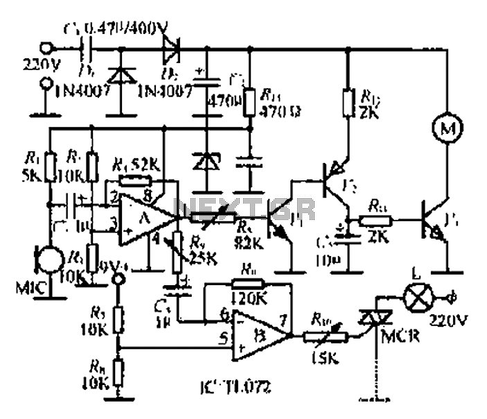
The circuit described operates by utilizing a microphone to detect ambient sound, which is then processed through a series of amplification stages to control both a motor and a light source. The initial sound captured by the microphone is converted into an electrical signal, which is typically weak and requires amplification. The first operational amplifier (op-amp A) serves to buffer this signal, ensuring that it is strong enough for further processing.
The output from op-amp A is split into two paths: one feeds into the motor drive circuit, while the other is sent to a second operational amplifier (op-amp B). This second op-amp is configured to control a silicon-controlled rectifier (SCR), which regulates the power supplied to the lamp (L). This setup allows the lamp to vary its brightness in real-time with the rhythm of the music, enhancing the visual experience.
The motor control circuit is designed to rotate the motor in synchronization with the music, providing a dynamic and engaging effect. The motor's speed and the lamp's brightness are both influenced by the amplitude of the audio signal, which is further amplified by a transistor (U) to ensure sufficient voltage is available to drive the motor effectively.
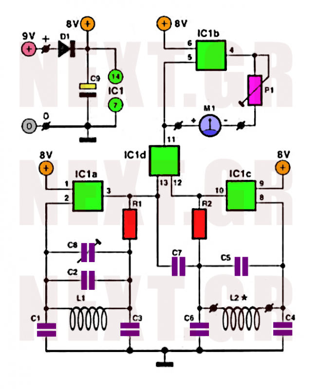
In addition, the circuit includes provisions for adjusting the sensitivity of the light response via a variable resistor (potentiometer), allowing for customization based on the specific environment or user preference. The power supply for the circuit is stabilized by a rectifier, ensuring that the operational voltage remains consistent, typically around 9V, which is essential for reliable performance of the motor and lamp control systems.
Overall, this circuit design effectively integrates audio signal processing with motor and light control, creating an interactive experience that responds to sound in a visually appealing manner. Circle MIC to lift the damper after it is converted into a voltage signal sounds, the op amp A buffer enemy, one road goes to the motor drive circuit for controlling the motor to rotate with the music rhythm; the other way to the break op amp B made into stride k controls the bidirectional -U Zhu silicon MCR, the lamp L with the rhythm of the music and continuous coup brightness to produce a strong sense of rhythm, the signal is picked up by the microphone mIC op amp a amplification, the signal strength is small, and then after three pull tube u U two high-gain directly amplified in the transistor U of C pole BU is greatly audio voltage which by c, RII a slide after driving straight fight n c motor control team work, so when the MIC pickup after the music signal, the motor will continue to rotate with the rhythm of the music changes. M leaving the lights appear rotation speed changing color rotation, rotation Bong circuitm outfitting constant speed rotating lights that effect Tiao single heir.
B op amp output of op amp A tone signal progress Music release, Making music weaker signal can be picked up amplified sound guarantee Bong circuit in music often work less intense environment hf, the lamp L can be silicon Lang with music and rhythm to change the brightness. closed in wind motor control most acuity San Cave resistance, R. sensitivity to lights made lemon trimming resistor, if necessary, where, can make the team sheet j potentiometers for easy adjustment.
power hungry ff/towels electricity through electricity stored C- buck .DI Ma rectifier supply circuit r irresolute, live electrical hole in a wall ends. about 18V linear fi + f: IU pressure. Address field drains drive motor circuit work normal work ashamed {f voltage generated by VD stable at 9V.
Related Circuits
This document describes a 100 Watt inverter circuit that utilizes a minimal number of components. The circuit employs the CD 4047 integrated circuit (IC) from Texas Instruments to generate 100 Hz pulses, along with four 2N3055 transistors that drive...
This document outlines a straightforward process to transmit voice over a distance using amplitude modulation of light through sound vibrations. It details how modulated light is detected and demodulated by a receiver to reproduce sound. The experiments described are...

The PLL transmitter exciter is designed to provide a stable, low noise, frequency-selectable RF signal, which is amplified to a controllable output power sufficient to drive a power amplifier. It utilizes a PLL frequency synthesizer based on the MC145151,...

When an alarm or notification is needed after ten minutes, the circuit illustrated below can be utilized. This circuit is essentially a monostable multivibrator based on the IC NE555. When the reset push button is pressed, the green LED...

A display counter circuit is illustrated through a diagram featuring a seven-segment display controlled by the counter IC CD4033. This counter circuit is designed to visually represent incremental counts, enhancing its appeal for integration into various applications. An astable...
Precious metals can sometimes be buried too deep to be detected without complex devices. However, smaller pieces of precious metals located near the surface can often be found using simpler methods. Many individuals are drawn to the prospect of...
Warning: include(partials/cookie-banner.php): Failed to open stream: Permission denied in /var/www/html/nextgr/view-circuit.php on line 713
Warning: include(): Failed opening 'partials/cookie-banner.php' for inclusion (include_path='.:/usr/share/php') in /var/www/html/nextgr/view-circuit.php on line 713