
Analog and digital electronic thermometer with LM35
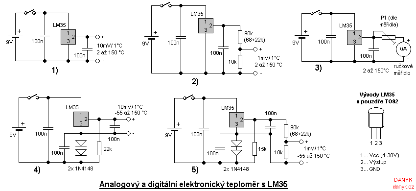
For a digital thermometer operating in the range of 2 to 150 °C, a simple schematic using the LM35 is presented. An adjustment circuit using a resistive divider allows for a transfer of 1 mV/°C. The circuit can measure ambient temperature, body temperature, and the temperature of various equipment such as CPUs and coolers. A digital thermometer capable of measuring from -55 to 150 °C requires a small negative voltage applied to pin 3, generated by the voltage drop across two diodes (e.g., 1N4148). This circuit can be powered by a voltage range of 5 to 30 V, with the diode voltage drop increasing the minimum required voltage by approximately 1 V. This design is applicable for measuring negative temperatures, such as outdoor temperatures or those in refrigerators and freezers, as well as in applications involving Peltier cells.
An analog electronic thermometer measuring between 2 and 150 °C is also feasible using the LM35 and an analog microamp meter. A trimmer (P1) can be adjusted to ensure the displayed meter value matches the actual temperature. The maximum deflection of the meter correlates with the temperature in °C, with the resistance (R) being the sum of the set value from P1 and the resistance of the analog meter coil in ohms. The current (I) represents the maximum deflection current of the meter in microamperes.Electronic thermometer has countless applications. Not everywhere can we use the standard mercury thermometer, for example, due to its size, frailty or the need to measure from the distance. The advantage of electronic thermometers are also small size and heat capacity of probes, faster response of the digital display and elimination
of toxic mercury. Its output also can be used to electronically processed, record the measured temperature, alarm when temperature is changing or work as a thermostat. circuit LM35: To build an electronic thermometer, i used LM35 integrated circuit, linear temperature sensor in TO92 - 3 pin housing that provides voltage proportional to temperature in degrees Celsius on its output.
Conversion of the output voltage is 10mV / °C and can therefore be used directly to display on the digital meter. As the display, ordinary multimeter or digital panel meter can be used. The thermometer can also be built into the multimeter. If matter that the displayed value has to be divided by 10, can be panel the meter or multimeter tightly associated with the meter modified to move the decimal point.
If we build thermometer as a removable extension of multimeter, you can use a resistive divider, and thereby obtain transfer 1mV / °C and display in °C. With a conventional multimeter, which has a range of 200mV to 0. 1 mV resolution, we get a thermometer with a resolution of 0. 1 °C. LM35 can be used in addition to building an analog thermometer with analog meter. I have added the circuit suppression capacitors 100n, because when using thermometer near EMI generation electronics there were deviations of up to 10 °C.
The thermometer I use, among other things to measure the temperature of heatsinks and switching power converters, and so it was not able to use it without these capacitors :). LM35 voltage range is 4 - 30V (recommended voltage up to 20V). The power supply I used is a 9V battery. Consumption is only about 50 - 100uA, allowing up to thousands of operating hours with one battery (!).
Some versions of LM35 have a limited temperature range, eg LM35C, LM35CA and provides measurements in the range -40 °C to +110 °C, LM35D between 0 °C to +100 °C. LM35 (no other letters), and LM35 measure in the full range of -55 to 150 °C. digital thermometer 2 to 150 °C: Figure 1 is the simplest schematic of thermometer with LM35 operating as a thermometer in the range 2 to 150 °C.
Figure 2 is its adjustment to the transfer of 1mV / °C using a resistive divider. The circuit can be powered from voltage 4 - 30V. The circuit can be used as the measurement of ambient temperature, body temperature, temperature of various equipment, coolers, CPU, etc. Digital Thermometer -55 to 150 °C: Figure 4 is the simplest connection with LM35 as thermometer in the range -55 to 150 °C.
Figure 5 is the adjustment to the transfer of 1mV / °C using a resistive divider. Negative temperature measurement requires a source of a small negative voltage to pin 3, which is applied to the second pin. Here the negative voltage is generated by voltage drop of two diodes (eg 1N4148). The circuit can be powered by voltage 5 - 30V (voltage drop of diodes increases the minimum required voltage of approximately 1V).
The circuit has application where it is necessary to measure negative temperature, for example, when measuring the outdoor temperature, the temperature in refrigerator, freezers, when working with Peltier cells, etc. analog electronic thermometer 2-150 °C: Figure 3 is the simplest schematic diagram of analog electronic thermometer with LM35 and analog uA meter measuring between 2 and 150 °C.
Can also be used for smaller temperature range as needed. Trimmer P1 can set so that the value displayed by the meter match the reality. The maximum deflection of the meter will respond temperature ( °C): The resistance R is the sum of the set value P1 and the resistance in ohms of analog metr coil. The current I is the current of maximum deflection of the meter in uA. 🔗 External reference
Related Circuits
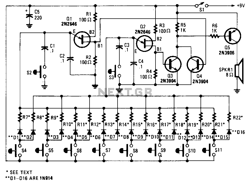
This circuit simulates the dual-tone drone sound produced by an unusual wind instrument. The urjunction transistors Q1 and Q2 are configured in similar audio-oscillator circuits. The frequency of each oscillator is determined by one of the two resistors selected...
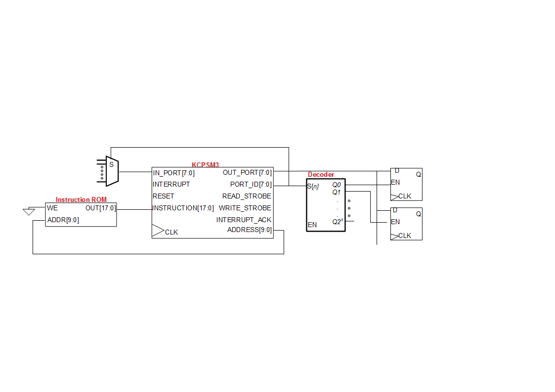
A small digital design utilizes a Xilinx Picoblaze softcore processor. Creating acceptable quality schematics has proven to be frustrating and time-consuming. Previous attempts to integrate existing schematics from LTSpice or Eagle into the documentation yielded unsatisfactory results, appearing fuzzy...
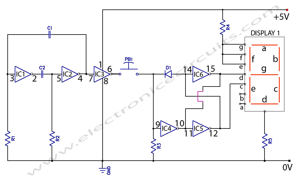
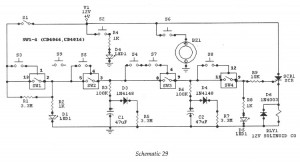
Electronic Coin Toss Circuit Diagram. This is an electronic coin toss circuit using one CD4049 IC (Hex inverting buffer and TTL driver). The electronic coin toss circuit utilizes the CD4049 integrated circuit, which serves as a hex inverting buffer...
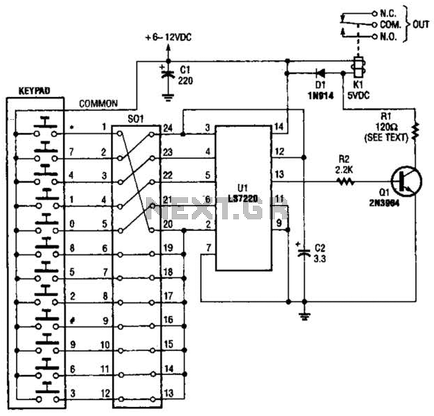
A block pinout diagram of the LS7220 keyless-lock IC is presented. The keypad must provide each key with a contact to a common connection. In this instance, the common connection is linked to the positive supply rail, allowing a...
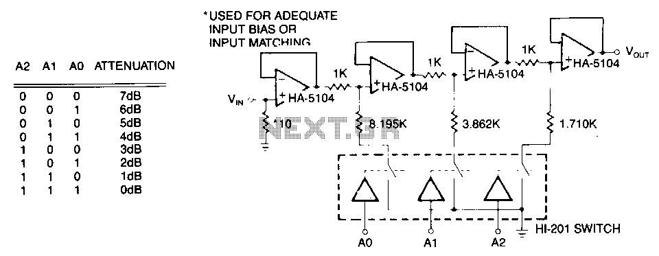
The first stage is a simple buffer used to isolate the signal source from the following attenuator stages. Each subsequent stage is preceded by a voltage divider formed by two resistors and a CMOS switch. When the CMOS switch...
Digital IC, Electronic Lock. This is an electronic code lock that can be used as a door latch or ignition key. The operation is quite intricate, which adds to the appeal of the circuit. The electronic code lock utilizes a...