
Analog-multiplexer-with-buffered-input-and-output
This circuit is utilized for analog signal selection or time division multiplexing. The feedback signal places the selected amplifier channel in a voltage follower (non-inverting unity gain) configuration, providing very high input impedance and low output impedance. The single package replaces four input buffer amplifiers, four analog switches with decoding, and one output buffer amplifier. For low-level input signals, gain can be added to one or more channels by connecting the negative inputs to a voltage divider between the output and ground. The bandwidth is approximately 8 MHz, and the output can transition between levels at about 15.0 V per microsecond. Expansion to multiplex 5 to 12 channels can be achieved by connecting the compensation pins of two or three devices together and using the output of only one of the devices, while ensuring that the enable input on the unselected devices remains low. Further expansion to 16 or more channels can be accomplished by connecting the outputs of four 4-channel multiplexers to the inputs of another 4-channel multiplexer. Differential signals can be processed by two identical multiplexers addressed in parallel. Inverting amplifier configurations may also be employed; however, the feedback resistors could induce crosstalk from the output to unselected inputs.
This circuit configuration is particularly advantageous in applications requiring high fidelity in signal selection and multiplexing. The voltage follower configuration ensures that the selected channel maintains signal integrity with minimal loading effects, making it suitable for high-impedance sources. The ability to configure multiple channels through cascading multiplexers allows for significant scalability, accommodating a wide range of input signals and enhancing versatility in complex systems.
The specified bandwidth of approximately 8 MHz indicates that the circuit can handle a variety of analog signals without significant distortion, making it suitable for audio, video, and data communication applications. The slew rate of 15.0 V/μs is sufficient for rapid signal changes, ensuring that the circuit can effectively track fast-moving signals.
For applications requiring more than 12 channels, the described method of cascading multiplexers provides a straightforward approach to expand the system’s capabilities. This modularity facilitates the design of larger systems without compromising performance. The use of differential signal handling enhances noise immunity, which is critical in environments with high electromagnetic interference.
Inverting amplifier configurations introduce additional complexity, but they can be beneficial in certain applications where signal inversion is required. Careful consideration must be given to the feedback resistors to mitigate potential crosstalk, which can degrade the performance of the circuit when multiple channels are in operation.
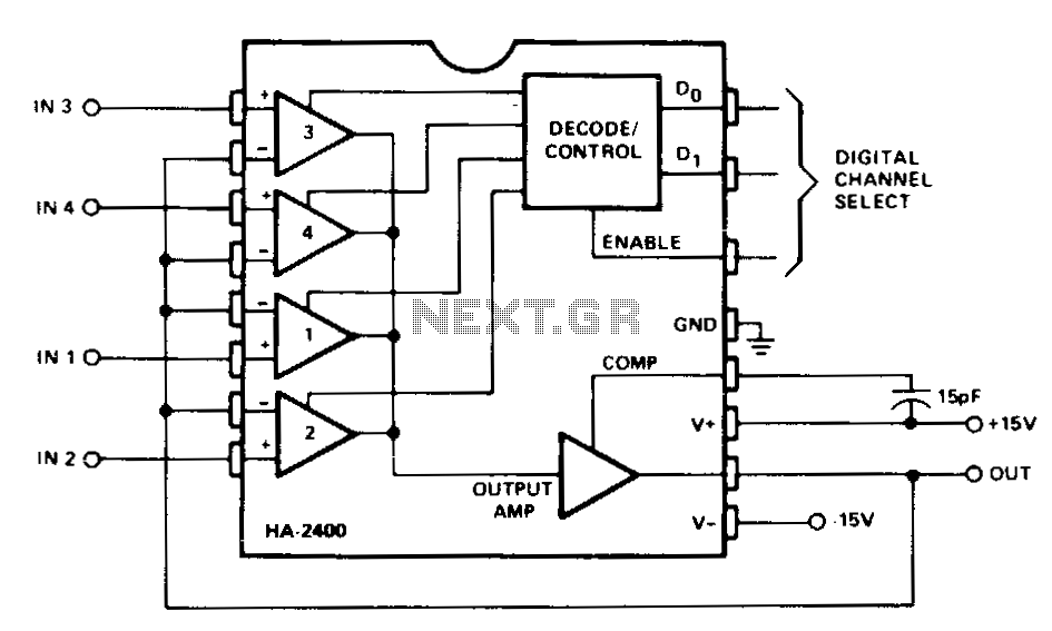
Overall, the circuit's design allows for flexible configurations, high performance, and scalability, making it a robust solution for analog signal selection and multiplexing in various electronic applications.· This circuit is used for analog signal selection or time division multiplexing. As shown, the feedback signal places the selected amplifier channel in a voltage follower (noninverting unity gain) configuration, and provides very high input impedance and low output impedance. The single package replaces four input buffer amplifiers, four analog switches with decoding, and one output buffer amplifier.
For low-level input signals, gain can be added to one or more channels by connecting the (-) inputs to a voltage divider between output and ground. The bandwidth is approximately 8 MHz, and the output will slew from one level to another at about 15.0 V per p.s. Expansion to multiplex 5 to J2 channels can be accomplished by connecting the compensation pins of two or three devices together, and using the output of only one of the devices.
The enable input on the unseiected devices must be low. Expansion to 16 or more channels is accomplished easily by connecting outputs of four 4-channel multiplexers to the inputs of another 4-channel multiplexer. Differential signals can be handled by two identical multiplexers addressed in paralleL Inverting amplifier configurations can also be used, but the feedback resistors might cause crosstalk from the output to unselected inputs.
🔗 External reference
This circuit configuration is particularly advantageous in applications requiring high fidelity in signal selection and multiplexing. The voltage follower configuration ensures that the selected channel maintains signal integrity with minimal loading effects, making it suitable for high-impedance sources. The ability to configure multiple channels through cascading multiplexers allows for significant scalability, accommodating a wide range of input signals and enhancing versatility in complex systems.
The specified bandwidth of approximately 8 MHz indicates that the circuit can handle a variety of analog signals without significant distortion, making it suitable for audio, video, and data communication applications. The slew rate of 15.0 V/μs is sufficient for rapid signal changes, ensuring that the circuit can effectively track fast-moving signals.
For applications requiring more than 12 channels, the described method of cascading multiplexers provides a straightforward approach to expand the system’s capabilities. This modularity facilitates the design of larger systems without compromising performance. The use of differential signal handling enhances noise immunity, which is critical in environments with high electromagnetic interference.
Inverting amplifier configurations introduce additional complexity, but they can be beneficial in certain applications where signal inversion is required. Careful consideration must be given to the feedback resistors to mitigate potential crosstalk, which can degrade the performance of the circuit when multiple channels are in operation.
Overall, the circuit's design allows for flexible configurations, high performance, and scalability, making it a robust solution for analog signal selection and multiplexing in various electronic applications.· This circuit is used for analog signal selection or time division multiplexing. As shown, the feedback signal places the selected amplifier channel in a voltage follower (noninverting unity gain) configuration, and provides very high input impedance and low output impedance. The single package replaces four input buffer amplifiers, four analog switches with decoding, and one output buffer amplifier.
For low-level input signals, gain can be added to one or more channels by connecting the (-) inputs to a voltage divider between output and ground. The bandwidth is approximately 8 MHz, and the output will slew from one level to another at about 15.0 V per p.s. Expansion to multiplex 5 to J2 channels can be accomplished by connecting the compensation pins of two or three devices together, and using the output of only one of the devices.
The enable input on the unseiected devices must be low. Expansion to 16 or more channels is accomplished easily by connecting outputs of four 4-channel multiplexers to the inputs of another 4-channel multiplexer. Differential signals can be handled by two identical multiplexers addressed in paralleL Inverting amplifier configurations can also be used, but the feedback resistors might cause crosstalk from the output to unselected inputs.
🔗 External reference