
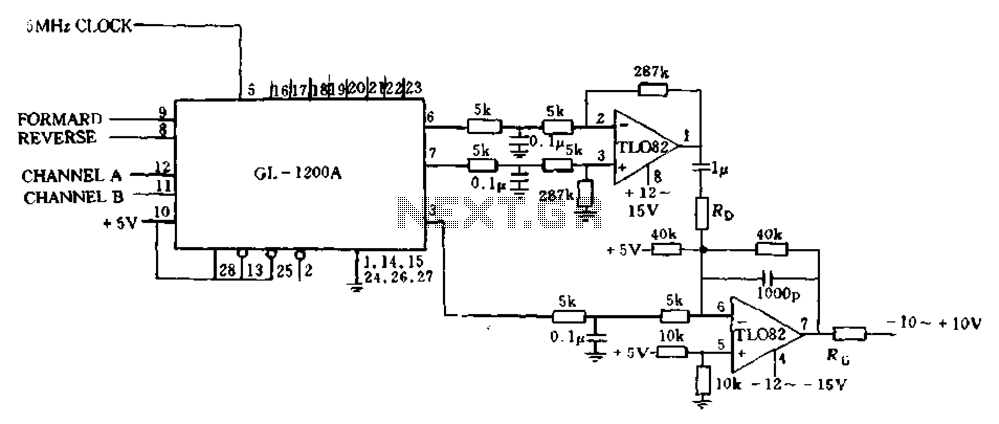
Analog PWM connection with FIG zps-101 interface
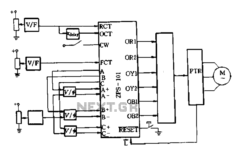
An AC-DC-AC circuit operates by converting alternating current (AC) to direct current (DC) and then back to AC, utilizing a power transistor as a key switching element. The schematic design, as outlined in Figure 6-10, incorporates analog control to facilitate precise voltage regulation. The circuit's primary function is to generate a voltage-controlled oscillator (VCO), which is integral for applications requiring frequency modulation.
The use of OCT (Operational Control Transistor) and FCT (Frequency Control Transistor) allows for the generation of oscillations at desired frequencies, while RCT (Resistor Control Transistor) can introduce delays in the OCT output, enhancing the circuit's adaptability. Additionally, the incorporation of monostable and RC (Resistor-Capacitor) circuits provides the capability for fine-tuning pressure adjustments, which can be critical in applications such as motor control or signal processing.
In this configuration, the circuit produces a three-phase square wave output (labeled a, B, C) that can be further extended into a six-phase square wave format. The delayed triggering mechanism generates specific phase relationships among the outputs, represented as +a, -B, +B, +C, etc. This flexibility allows for the integration of various circuit designs, including the phase-shift trigger KJ009, which can modulate the phase shift control voltage effectively.
The phase-shifting capability is crucial, as it provides a means to achieve a 180-degree phase difference between two pulse outputs. This feature is essential in applications requiring synchronized operations, such as in three-phase motor drives or in systems where precise timing is necessary. The voltage signals generated must be carefully regulated according to the operational frequency of the function generator, ensuring that the entire system remains in synchronization and operates efficiently. Proper synchronization is vital for maintaining the integrity of the output signals and ensuring that the circuit performs as intended across varying operational conditions.AC-DC-AC circuit when the power transistor as a switching device with analog control if built according to Figure 6-10 recommended wiring. Generating a voltage controlled oscil lator OCT and FCT, RCT available OCT delay ., (with monostable and RC circuits may be) can be obtained at this time for adjusting the pressure, do not use the VCT, which is produced by using the FCT Three-phase square wave a, B, C forming the extension of the six-phase square wave a delayed triggered +, a, B-, B, c +, C and then into the can. This could be the choice of any circuit, such as phase-shift trigger KJ009. with phase shift control voltage, each piece can be obtained 180. the difference between the two phase shifting pulse, voltage signal shall be approved by the regulator according to the frequency of the function generator needs access to synchronization adjustment.
Related Circuits
This is a nice design for people who have no tachometer in the car or on the bike. The circuit uses two ICs: an NE 555 and a CA 3140. The input of the circuit is connected to the...
If the sensor system requires an active supply, a single pair of cables can be utilized to transmit both the power supply and the output signal. This approach simplifies the overall system. In sensor systems that necessitate an active power...
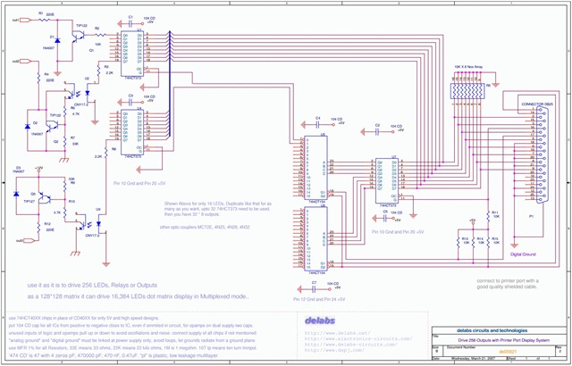
The following schematic illustrates the design of a Parallel Port Interface Circuit Diagram utilizing the 74HCT373. The 74HC/HCT373 are high-speed silicon-gate CMOS devices that are pin-compatible with low-power Schottky TTL (LSTTL). This parallel port interface circuit can drive 256...

The 040904C version of the code has a larger UART receive buffer and supports two pushbuttons that send either an ASCII "R" ($52) or an ASCII carriage. Something to keep in mind when using AVR controllers that support 16-bit...
The circuit presented on this page attempts to be an interface to convert pulses such as provided by a Basic Stamp or R/C receiver to a dual PWM (Pulse Width Modulation) signal required by an H-bridge. The simplest circuit...
The error processing segment is converted into a pulse width modulated (PWM) signal output from 3 feet (MC signal). Additionally, the differential position error is calculated, which represents the small velocity, from 6 to 7 feet, selected as a...