
Analog to Digital Converter
The analog-to-digital (A-D) and digital-to-analog (D-A) conversion processes are fundamental in bridging the gap between continuous and discrete signal representations. An A-D converter samples an analog signal at specific intervals, quantizing its amplitude into discrete values. The process begins with the sampling of the signal, which is governed by the Nyquist theorem, dictating that the sampling frequency must be at least twice the maximum frequency present in the analog signal to avoid aliasing. Each sampled value is then quantized, typically using a fixed number of bits, which determines the resolution of the conversion. For instance, an 8-bit quantization yields 256 discrete levels, while a 16-bit quantization provides 65,536 levels, allowing for finer representation of the analog signal.
The quantization process introduces a quantization error, which is the difference between the actual analog value and the quantized digital value. This error can be minimized by increasing the number of bits used in the quantization process. Once the signal is quantized, it is encoded into a binary form, which can be easily processed and transmitted in digital systems.
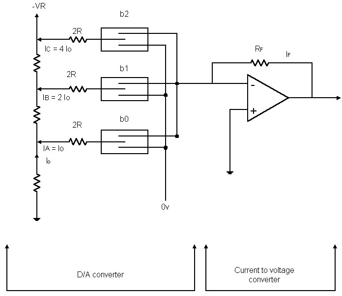
Conversely, the D-A conversion process involves reconstructing the analog signal from its digital representation. This is achieved through a series of steps that include decoding the digital signal back into its quantized levels and then smoothing these levels into a continuous signal using a reconstruction filter, typically a low-pass filter. The filter helps to eliminate high-frequency components introduced during the quantization process, resulting in a smooth analog output that closely approximates the original signal.
Both A-D and D-A converters are critical components in various applications, including audio processing, telecommunications, and data acquisition systems. The choice of converter type and specifications depends on the application requirements, including bandwidth, resolution, and the nature of the signals being processed. Understanding the properties and limitations of both analog and digital signals is essential for designing effective signal processing systems that meet specific performance criteria.Before examining the various analog to d igital (A-D) and digital to analog (D-A) conversion processes it is useful to review the properties of each type of representation; in particular this may help select the representation most suited to the problem at hand. An analog signal is a signal whose value varies continuously with time, its instantaneous amplitude itself varying continuously within a limited range.
The simplest example is that of a sinusoidal signal Asin(w t + f ), whose instantaneous value covers all the values within the range (-A, +A). An analog signal may very often be expressed as a weighted sum of sinusoidal signals. The analog signal is a simple type of signal which can quite conveniently be transmitted, but its simplicity results in several drawbacks.
It is sensitive to parasitic signals and its amplitude or phase can be distorted by the transmitting system. When it undergoes such operations as analog multiplication the accuracy with which the signal is known is often reduced.
Moreover it is difficult to store an analog signal. On the other hand a digital signal usually appears as a series of symbols. Thus, in a binary system a signal consists of a series of numbers, each of which is 0 or 1, that may be given physical form by the absence or presence of pulses. It can be said that the signal is represented by a word of a given format that is of a given structure.
The digital signal represents the value of a quantity at a specific instant. It is not a continuous signal and since the symbols making up this signal (usually numbers) can only vary by `steps` the value represented by the signal must, perforce, be discrete. These difference from the analog signal, which may appear to be obstacles, are largely compensated by the advantages gained by the digital representation.
First of all a digital signal is far less sensitive to the imperfections of the transmitting system (distortion, noise) since it is only necessary to detect the pulses in order to obtain the information, their precise characteristics (amplitude, duration) not being taken into account. During the various operations the accuracy of the signal is maintained (if some of the truncating that is sometimes carried out is ignored).
On the other hand the pass band required for transmitting digital information is much greater than the pass band needed for an analog representation of the information. Thus, each representation has its advantages and disadvantages; the choice of one or other method must take into account the nature of the signal available, the possibility of introducing a digital process, the likelihood of transmitting the information, etc.
Information processing systems may be divided into analog systems and digital systems. In the first case the systems handle signals that vary in a continuous way whereas in the second case the systems handle discrete variables called digital numbers. Any digital treatment of an analog signal first requires an analog to digital conversion operation. If it is desired to recover the processed information in its initial analog form then the inverse conversion operation is needed.
It is necessary now to examine in some detail the operations required by the conversion processes. Let x(t) represent a given analog signal and let x*(t) be the series of discrete values of the given signal taken at regular time intervals of period Te. The operat 🔗 External reference
Related Circuits
This electronic clock comprises the LM8365 and the LDD640R displays. The LM8365 can show the hour/minute and month/day. Users can set two alarm outputs, AD1 and AD2, by pressing either the 12h or 24h button. The operating voltage range...
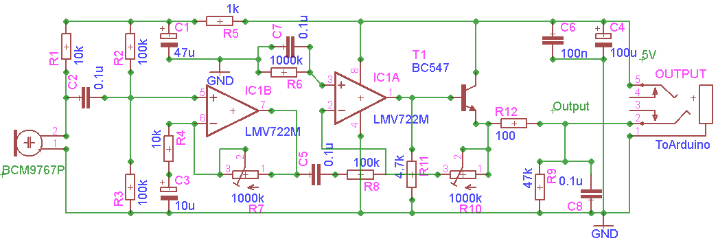
The GVI Digital Remote Control for DSLR cameras represents an advancement over previous remote controls for the Canon EOS 450D. This remote utilizes the AVR Microcontroller ATmega328 and is programmed using the Arduino IDE. It serves as a tool...
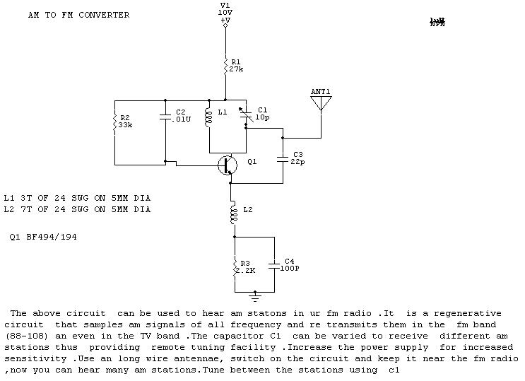
The circuit described is designed to enable the reception of AM stations on an FM radio. It operates as a regenerative circuit, sampling AM signals across various frequencies and retransmitting them within the FM band (88-108 MHz) and even...
This chapter shows how to connect an analogue signal to a PIC. An analogue signal is similar to a sine wave and is generally less than 5v (5,000mV) in amplitude. Low-level signals are generally expressed in mV, to make...
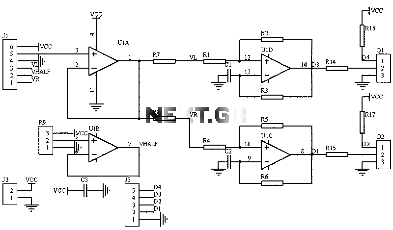
The image illustrates a circuit that utilizes a linear potentiometer (or linear Hall element) to control the PWM generation for two chassis drive motors in a gamepad or joystick used in model aircraft. J1 represents the handle of the...
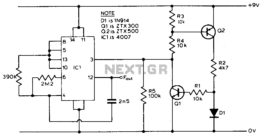
The circuit utilizes the principle that the forward voltage of a silicon diode changes in a relatively linear manner with temperature when supplied by a constant current source. Diode D1 and resistor R2 create a potential divider connected to...
Warning: include(partials/cookie-banner.php): Failed to open stream: Permission denied in /var/www/html/nextgr/view-circuit.php on line 713
Warning: include(): Failed opening 'partials/cookie-banner.php' for inclusion (include_path='.:/usr/share/php') in /var/www/html/nextgr/view-circuit.php on line 713