
analog to digital converter module
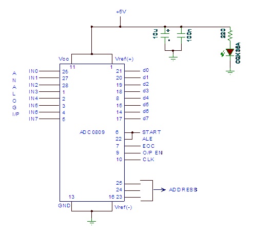
The ADC 0809 is a widely used analog-to-digital converter that facilitates the conversion of analog signals into digital form, suitable for processing by a microcontroller. The architecture of the ADC 0809 consists of a series of functional blocks, including an analog input stage, a sample-and-hold circuit, a successive approximation register (SAR), and a digital output stage.
The pin configuration of the ADC 0809 is critical for its operation. The 8 analog input pins (labeled A0 to A7) allow for the connection of various analog signal sources. The digital output pins provide the converted binary data. The control pins, including the start of conversion (SOC) and end of conversion (EOC), are essential for synchronizing the conversion process with the microcontroller.
In practical applications, the ADC 0809 is typically interfaced with a microcontroller through its data and control lines. The microcontroller sends a signal to initiate the conversion process via the SOC pin. Once the conversion is complete, the EOC pin goes high, indicating that the digital output is ready for retrieval. The microcontroller can then read the converted data from port 0, which corresponds to the binary representation of the analog input signal.
The use of filter capacitors, such as the 10µF and 100µF capacitors mentioned, is crucial in ensuring the integrity of the analog signal prior to conversion. These capacitors smooth out voltage fluctuations and suppress high-frequency noise, which can adversely affect the accuracy of the conversion process. The LED indicator provides a visual confirmation of the circuit's operational status, allowing for quick diagnostics and troubleshooting.
Overall, the ADC 0809 is an essential component in systems requiring precise analog-to-digital conversion, enabling microcontrollers to process real-world signals effectively.Analog to Digital converter modules are used in Micro controller based projects where the analog signals are required to be converted into digital signal for further processing in Micro controller. The integrated chip used for this purpose is 0809 ADC. This post describe briefly the PIN diagram, block diagram and details of this specified chip her e. The ADC totally consists of 28 pins with 8 inputs and 8 outputs. The output from the filter is given to pin 26 of ADC 0809 shown in the figure above. The address channels A, B, C are grounded so that channel 1 is enabled. The digitized output from the converter is given to port 0 of micro controller. The control signals from the ADC are given to port 2 of the Microcontroller. This circuit follows the principle of successive approximation method and when the start of conversion goes high, it marks the beginning of the process and high end of conversion marks the end of it. The two capaciors 10F and 100F acts as filter. The filter capacitors in the circuit remove the low and high frequency noises. The LED is used to check the proper functioning of the circuit. 🔗 External reference
Related Circuits
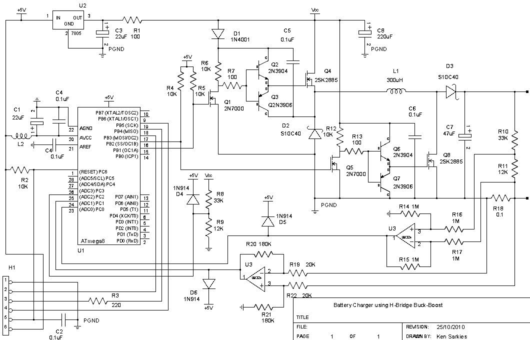
The buck-boost converter is valuable when the output and/or input voltages fluctuate significantly, necessitating the use of a buck converter at times and a boost converter at others. An example, which will be elaborated on in a future project,...
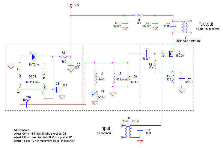
Here is my design for a modern receiving converter for pre-war FM sets. Accordingly, this article presents a design for listening to present day FM stations on a prewar FM set based on a MOSFET transistor and a TTL...
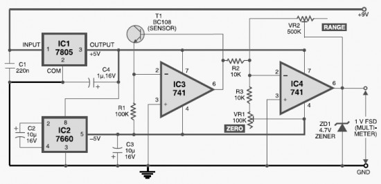
This DIY digital thermometer circuit can measure temperatures up to 150°C with an accuracy of ±1°C. The temperature is displayed on a 1V full scale deflection. The digital thermometer circuit is designed to provide accurate temperature readings within a specified...
This circuit diagram illustrates the conversion of a speaker into a microphone. When sound waves impact the diaphragm of a speaker, fluctuations occur in the coil, generating an induced voltage. This induced voltage is typically substantial but low in...
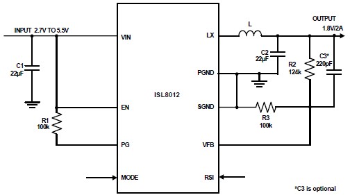
The ISL8012 is a high-efficiency, monolithic, synchronous step-down DC-DC converter that can be designed into a simple electronic project. It supports a maximum continuous output current of up to 2A from an input supply range of 2.7V to 5.5V....

This digital thermometer circuit diagram utilizes a common 1N4148 diode as the temperature sensor. The diode's temperature coefficient of -2 mV/°C is leveraged to create an accurate electronic thermometer. A digital multimeter is employed to display the measured temperature,...
Warning: include(partials/cookie-banner.php): Failed to open stream: Permission denied in /var/www/html/nextgr/view-circuit.php on line 713
Warning: include(): Failed opening 'partials/cookie-banner.php' for inclusion (include_path='.:/usr/share/php') in /var/www/html/nextgr/view-circuit.php on line 713